
Full-current composite high-voltage direct current transmission system

A high-voltage direct current and power transmission system technology, applied in the direction of power transmission AC network, etc., can solve problems affecting system safety and stability, difficult coordination control, commutation failure, etc., to solve commutation failure, eliminate commutation failure, and high reliability Effect

Inactive Publication Date: 2014-03-19
POWER GRID TECH RES CENT CHINA SOUTHERN POWER GRID +1
View PDF2 Cites 7 Cited by
  • Summary
  • Abstract
  • Description
  • Claims
  • Application Information

AI Technical Summary

Problems solved by technology

However, commutation failures are prone to occur during the inverter operation of thyristor converters. For multi-circuit DC centralized feeding into the grid, AC system failures may cause multiple converter stations to fail commutation at the same time, causing a huge impact on the grid and seriously affecting the safety of the system. Stablize
[0003] The use of voltage source converters based on fully-controlled power electronic devices in the inverter station can solve the problem of commutation failure, but it also brings new problems. The inverter station uses the DC side as a voltage source, and the thyristor The rectifier station of the converter regards the DC side as a current source, and the two stations operate in different modes, which makes it difficult to coordinate and control

Method used


Image

  • Full-current composite high-voltage direct current transmission system
  • Full-current composite high-voltage direct current transmission system

Examples


Embodiment

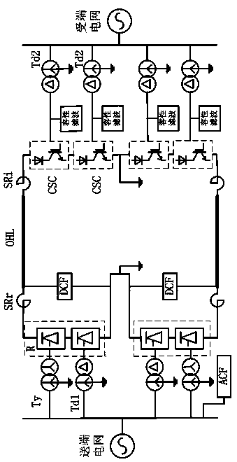
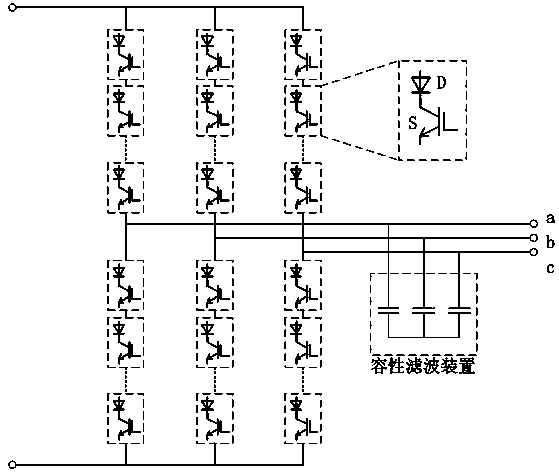
[0015] The full-current compound high-voltage direct current transmission system of the present invention includes a rectifier station, an inverter station and overhead power transmission lines. The rectifier station adopts a thyristor converter, and the positive and negative poles of the thyristor converter contain at least one twelve-pulse thyristor converter; the inverter station adopts a current source converter based on a fully-controlled power electronic device, and the positive and negative poles Both contain two series-connected current source converters; the connection points of the positive and negative poles of the rectifier station and the inverter station are connected to the ground pole or The station is connected to the ground network, and the rectifier station and the inverter station are connected through overhead power transmission lines.

[0016] Both the rectification station and the inverter station are equipped with smoothing reactors, each pole of the re...


PUM


Abstract

The invention relates to a full-current composite high-voltage direct current transmission system. The full-current composite high-voltage direct current transmission system includes a rectification station, an inversion station and an overhead power transmission line; the rectification station adopts thyristor converters; the positive pole and negative pole of the rectification station both comprise a twelve-pulse thyristor converter; the inversion station adopts fully-controlled power electronic device-based current source-type converters; the positive pole and negative pole of the inversion station both include two series-connection current source-type converters; positive and negative pole connection points of the rectification station and the inversion station are connected with a grounding pole or an intra-station grounding grid according to situations in which the direct current transmission system is in bipolar, mono-polar ground return or mono-polar metal return operation modes; and the rectification station is connected with the inversion station through the overhead power transmission line. The full-current composite high-voltage direct current transmission system of the invention is advantageous in flexible operation mode and high reliability. The full-current composite high-voltage direct current transmission system of the invention is especially suitable for long-distance high-voltage direct current overhead transmission, and is also particularly applicable to the upgrading and reconstruction of the existing full-thyristor type high-voltage direct current transmission. The full-current composite high-voltage direct current transmission system is further advantageous in convenience and practicability.

Description

technical field [0001] The invention is a full-current compound high-voltage direct current power transmission system capable of solving the problem of phase commutation failure on the inverter side, and belongs to the innovative technology of the compound high-voltage direct current power transmission system. Background technique [0002] The HVDC power transmission system using thyristor converters in both the rectifier station and the inverter station has the advantages of less damage, relatively low cost, and high reliability. However, commutation failures are prone to occur during the inverter operation of thyristor converters. For multiple DC centralized feed-in grids, AC system failures may cause multiple converter stations to fail commutation at the same time, causing a huge impact on the grid and seriously affecting the safety of the system. Stablize. [0003] The use of voltage source converters based on fully-controlled power electronic devices in the inverter st...

Claims


Application Information

Patent Timeline
IPC IPC(8): H02J3/36
CPCY02E60/60
Inventor 饶宏许树楷陈俊黎小林朱喆罗雨
Owner POWER GRID TECH RES CENT CHINA SOUTHERN POWER GRID
Learn More