
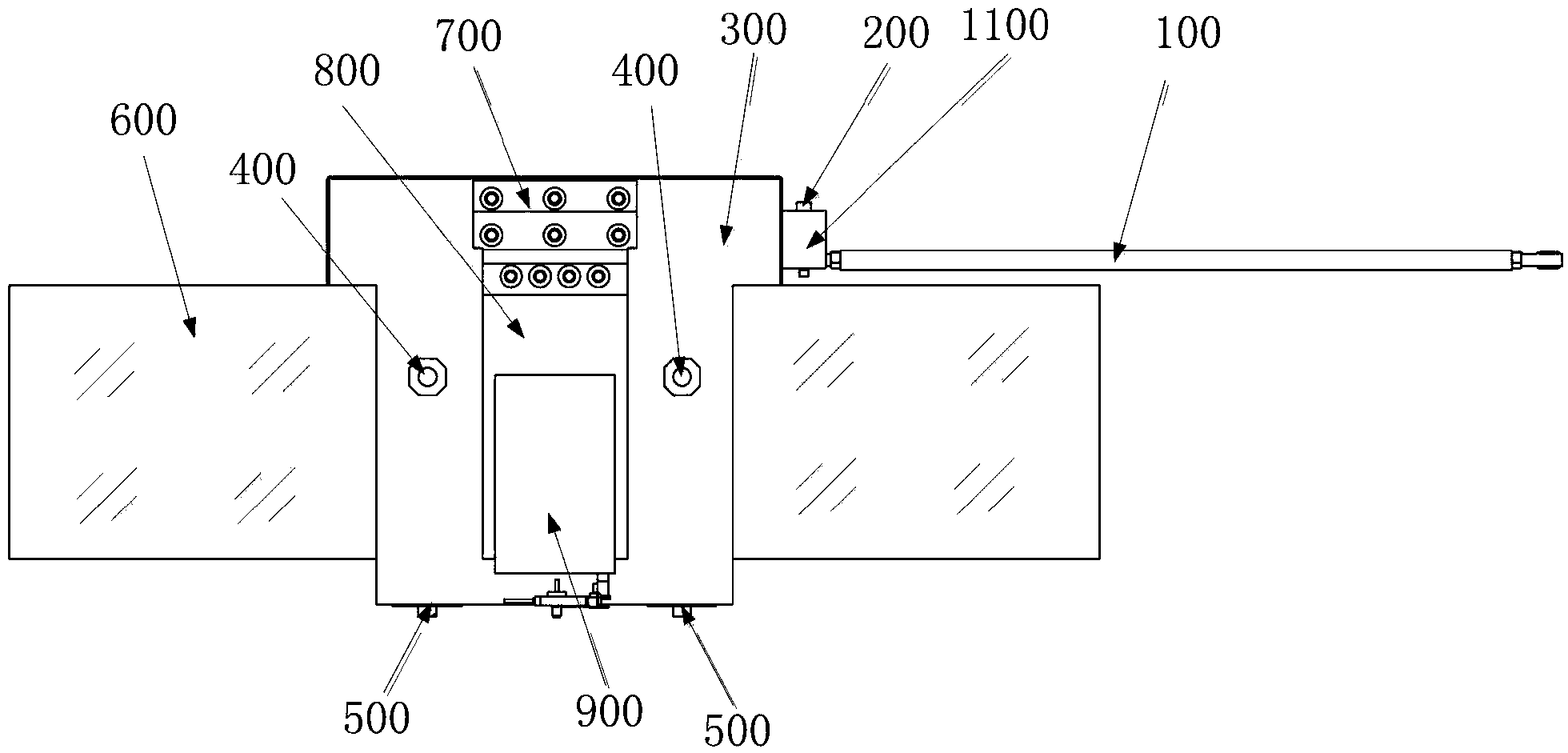
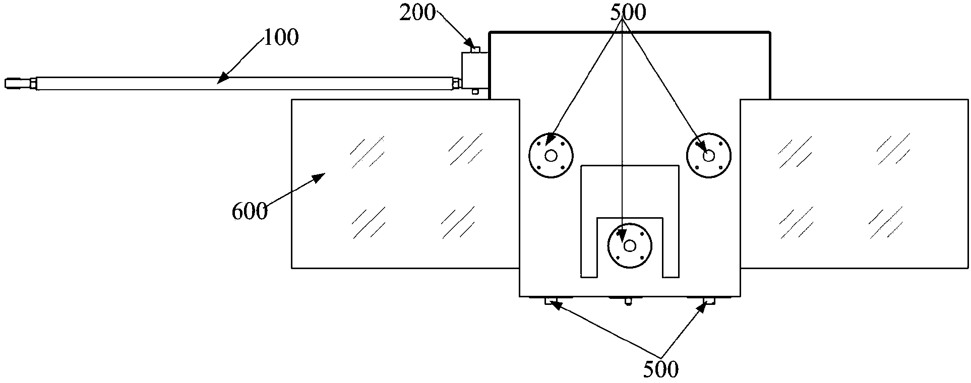
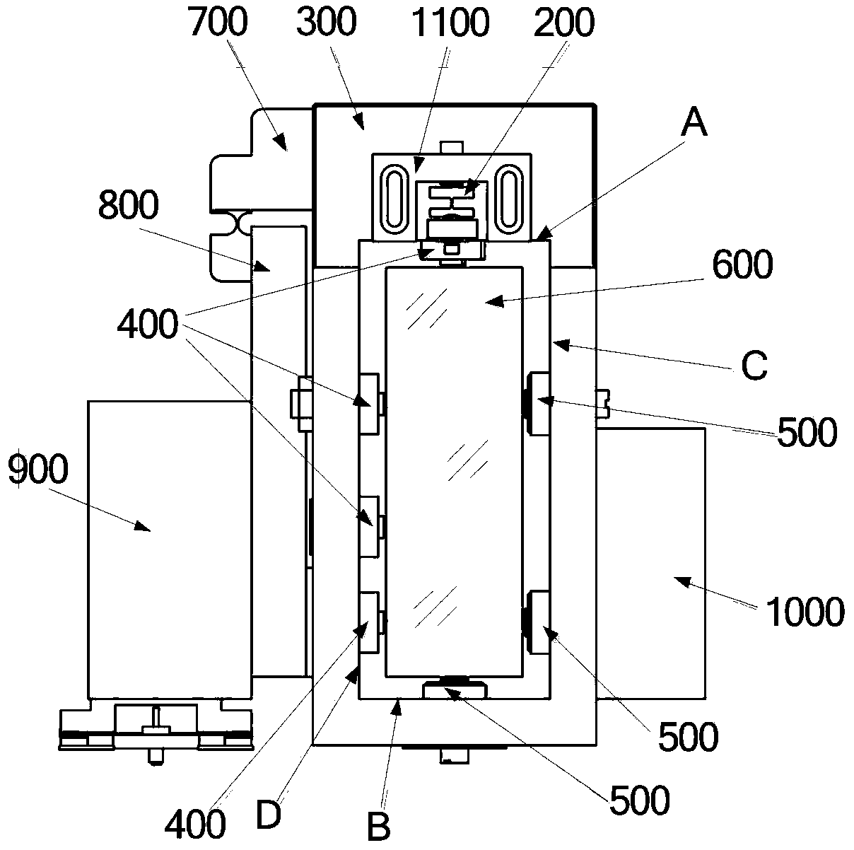
Large-area grating ruling cutter frame system

A grating scribing knife, large-area technology, applied in diffraction grating and other directions, can solve the problems affecting the running accuracy of the diamond scribing knife, the sliding block is prone to rotation, and the glass guide rail is deformed greatly.

Active Publication Date: 2014-03-19
CHANGCHUN INST OF OPTICS FINE MECHANICS & PHYSICS CHINESE ACAD OF SCI
View PDF4 Cites 14 Cited by
  • Summary
  • Abstract
  • Description
  • Claims
  • Application Information

AI Technical Summary

Problems solved by technology

[0003] In the existing large-area grating marking technology, the tool holder system uses a concave slider to run on the glass guide rail; since the lower end of the slider has no closing force, the slider is prone to rotation, which affects the operation of the diamond cutter Accuracy; Moreover, the connecting rod of the existing tool post system is fixedly connected to the slider. When the direction of the external driving force is inconsistent with the direction of movement of the slider, the deformation of the glass guide rail is large and the actual trajectory of the slider is likely to be greatly different from the ideal trajectory. Deviation; in addition, the existing connection between the slider and the tool holder mounting plate is a hinge structure, because there is an axial gap error between the rotating shaft and the bushing of the hinge structure, it is difficult to ensure the long-term stability of the knife operation, It is not conducive to engraving large-area gratings with uniform groove and groove spacing

Method used


Image

  • Large-area grating ruling cutter frame system
  • Large-area grating ruling cutter frame system
  • Large-area grating ruling cutter frame system

Examples


Embodiment Construction

[0038] In order to make the object, technical solution and advantages of the present invention clearer, the present invention will be further described in detail below in conjunction with the accompanying drawings and embodiments. It should be understood that the specific embodiments described here are only used to explain the present invention, not to limit the present invention.

[0039] In addition, the technical features involved in the various embodiments of the present invention described below can be combined with each other as long as they do not constitute a conflict with each other.

[0040] In the description of the present invention, the orientation or positional relationship indicated by the terms "inner", "outer", "longitudinal", "transverse", "upper", "lower", "top", "bottom" etc. are based on the drawings The orientations or positional relationships shown are only for the convenience of describing the invention and do not require the invention to be constructed...


PUM


Abstract

The invention discloses a large-area grating ruling cutter frame system, relates to the technical field of grating ruling, and solves a problem that the long-term operation stability of a cutter is difficult to be ensured because connection between a sliding block and a cutter frame mounting plate is of a hinge structure and an axial gap error exists between a rotating shaft and a shaft sleeve of the hinge structure. The large-area grating ruling cutter frame system comprises a glass guide rail, a sliding block, a connecting rod, a ruling cutter frame and a cutter frame mounting frame, wherein the sliding block slides along the glass guide rail, the sliding block is of an all-closed hollow shape, sleeved on the glass guide rail and provided with guide sliding feet and elastic sliding feet, and the guide sliding feet and the elastic sliding feet are all contacted with the external surface of the glass guide rail; the connecting rod is connected with an external driving mechanism and the sliding block, and the driving mechanism pushes and pulls the connecting rod so as to drive the sliding block to slide along the glass guide rail; and the cutter mounting plate is used for mounting a cutter frame, the upper end of the cutter frame mounting plate is fixedly connected with the sliding block, and the lower end of the cutter frame mounting plate is provided with the guide sliding feet. The large-area grating ruling cutter frame system is conducive to reducing the scribed line position error during grating ruling and improving the large-area grating ruling precision.

Description

technical field [0001] The invention relates to the technical field of grating scribing, in particular to a large-area grating scribing tool holder system. Background technique [0002] The mechanical scribing method is one of the main methods for making gratings. This method requires a diamond scribe to extrude a series of equally spaced scribe lines on the surface of the aluminum film. The ideal shape of each scribe line is a straight line. The long-term running accuracy of the tool holder system is extremely high. [0003] In the existing large-area grating marking technology, the tool holder system uses a concave slider to run on the glass guide rail; since the lower end of the slider has no closing force, the slider is prone to rotation, which affects the operation of the diamond cutter Accuracy; Moreover, the connecting rod of the existing tool post system is fixedly connected to the slider. When the direction of the external driving force is inconsistent with the dir...

Claims


Application Information

Patent Timeline
Patent Type & Authority Applications(China)
IPC IPC(8): G02B5/18
Inventor 李晓天于海利唐玉国杨超齐向东
Owner CHANGCHUN INST OF OPTICS FINE MECHANICS & PHYSICS CHINESE ACAD OF SCI
Learn More