
Magnetostriction type dual-cavity membrane type micropump

A technology of magnetostriction and magnetostrictive rods, which is applied in the direction of pumps, liquid displacement machines, pumps with flexible working elements, etc., can solve the problem of a single liquid, achieve strong self-priming ability, low driving voltage, and ensure The effect of stability

Active Publication Date: 2014-03-12
JIANGSU UNIV
View PDF6 Cites 7 Cited by
  • Summary
  • Abstract
  • Description
  • Claims
  • Application Information

AI Technical Summary

Problems solved by technology

Giant magnetostrictive materials have the advantages of rapid response and large strain, and are widely used in various micropumps. The existing patent CN 1908431A for related micropumps provides a membrane micropump driven by giant magnetostriction. The pump uses a single The small deformation of the magnetostrictive rod acts on the elastic diaphragm through the displacement amplification mechanism, so that the elastic diaphragm causes the volume of the cavity to change, and realizes the transportation of a small amount of liquid. The disadvantage of this device is that only one-stage telescopic rod is used. Can only complete the output of a single liquid
At present, there is no report on micropumps using magnetostrictive actuators to complete the fixed ratio and mixed delivery of two trace liquids.

Method used


Image

  • Magnetostriction type dual-cavity membrane type micropump
  • Magnetostriction type dual-cavity membrane type micropump
  • Magnetostriction type dual-cavity membrane type micropump

Examples


Embodiment Construction

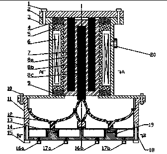
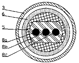
[0016] See attached figure 1 , an embodiment of a magnetostrictive double-cavity membrane micropump of the present invention can realize the mixed delivery of two liquids in equal quantities. The overall size of the micropump is Φ50×55 mm. The micropump includes a pump body, The displacement amplifying mechanism 12 and the magnetostrictive driver have three parts.

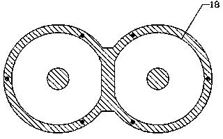
[0017] The pump body part includes connecting body 11, elastic diaphragm 13, gasket 14, screw 15, left inlet valve 16a, left outlet valve 17a, right inlet valve 16b, right outlet valve 17b, pump casing 18, spring 19. Such as figure 1 As shown, the pump housing 18 contains two equal-volume cavities, and two springs 19 are placed at the protrusions of the central part of the two cavities; the inlet valve 16 and the outlet valve 17 are connected with the left and right cavities of the pump housing 18 respectively. The body is connected, and sealant is applied at the connection position to ensure its tightness;...


PUM


Abstract

The invention discloses a magnetostriction type dual-cavity membrane type micropump, and belongs to the field of micro fluid control. The magnetostriction type dual-cavity membrane type micropump mainly comprises a magnetostriction rod set, a sleeve, a permanent magnet, a coil rack which a coil is wound around, a displacement amplifying mechanism, elastic membranes and a pump case. An upper polarity rod and a lower polarity rod are arranged at corresponding positions inside the sleeve respectively. The sleeve is arranged in a center through hole of the coil rack which the coil is wound around. After a control current flows into the coil, an external magnetic field is changed to cause magnetostriction rods to deform; the displacement amplifying mechanism deforms elastically, wherein a left kind semiellipse elastic deformation amount and a right kind semiellipse elastic deformation amount of the displacement amplifying mechanism are different; the displacement amplifying mechanism extrudes the elastic membrane on a left cavity and the elastic membrane on a right cavity of a pump body respectively through column heads, different deformation amounts of the elastic membranes cause different changes in the volumes of the two airtight cavities, and therefore it can be realized that micro fluids inside the two cavities are conveyed according to a fixed ratio. The magnetostriction type dual-cavity membrane type micropump has the advantages of being small in size, low in flow, capable of being driven at a low voltage, and capable of conveying two fluids in a hybrid mode according to a fixed ratio.

Description

technical field [0001] Micro-flow The invention belongs to the field of micro-fluid control, and relates to a fluid delivery device capable of mixing and transporting two micro-liquids in a fixed ratio. Background technique [0002] In the field of medicine, the treatment of diseases often uses the mixed delivery of two or three liquid medicines; in addition, for diseases such as diabetes, injecting a large dose of insulin at one time not only causes waste, but also the time of drug action is short ; At the same time, the delivery of some drugs (such as cardiac drugs, vasoactive drugs) requires accuracy and stable input flow rate. That is to say, in special occasions, the rationality of the drug delivery method and dosage will affect the effect of disease treatment to a certain extent, and reasonable control of drug ratio and flow rate plays an important role in the treatment of diseases. [0003] The micropump can control the input speed to ensure the quantitative deliv...

Claims


Application Information

Patent Timeline
Patent Type & Authority Applications(China)
IPC IPC(8): F04B43/04
Inventor 姜银方郭华杰姜文帆严琴张伟严有琪
Owner JIANGSU UNIV
Learn More