
Multi-spray-head electrostatic spinning device

An electrospinning and multi-nozzle technology, applied in textiles and papermaking, filament/thread forming, fiber processing, etc., can solve the problems of high difficulty in providing high-voltage power supply, affecting the quality of nanofibers, increasing jet instability, etc., to achieve Reduce electrostatic interference, reduce electrostatic interference, and reduce the effect of surface charge density

Active Publication Date: 2014-03-12
XIAMEN UNIV
View PDF5 Cites 24 Cited by
  • Summary
  • Abstract
  • Description
  • Claims
  • Application Information

AI Technical Summary

Problems solved by technology

At present, most of them use standard injection spinning nozzles as nozzles, but it is relatively difficult to provide high-voltage power supply to each spinning nozzle in this way. It is common to provide high-voltage power supply uniformly by winding wires around each spinning nozzle. This method is cumbersome and inconvenient, especially impractical when dealing with a large number of spinning nozzles
Moreover, the multi-spinning nozzle system is adopted, and each jet has the whip instability similar to the electrospinning of a single spinning nozzle system, and electrostatic repulsion will also occur between the jets, causing the jet to tilt, increasing the jet instability. Stability, the spun nanofibers are not uniform, which affects the quality of the prepared nanofibers

Method used


Image

  • Multi-spray-head electrostatic spinning device
  • Multi-spray-head electrostatic spinning device

Examples


Embodiment Construction

[0013] The present invention will be further described below with reference to the accompanying drawings and embodiments.

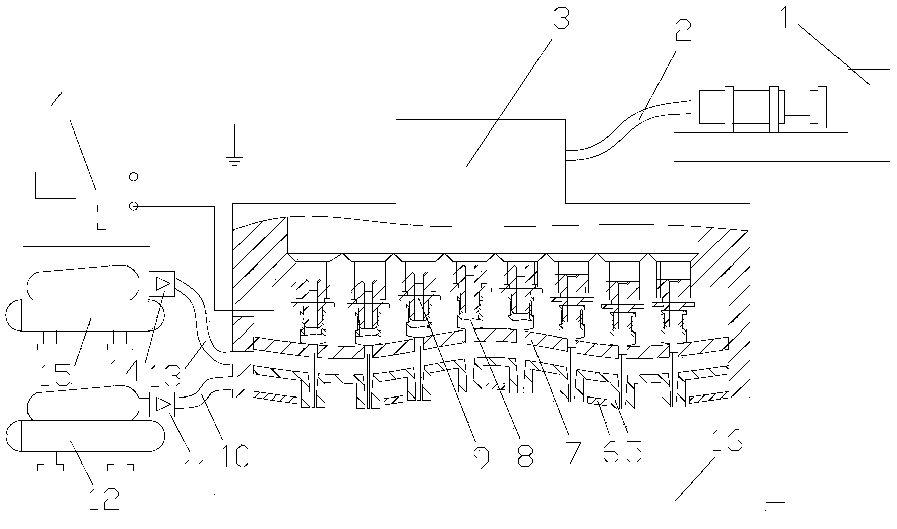
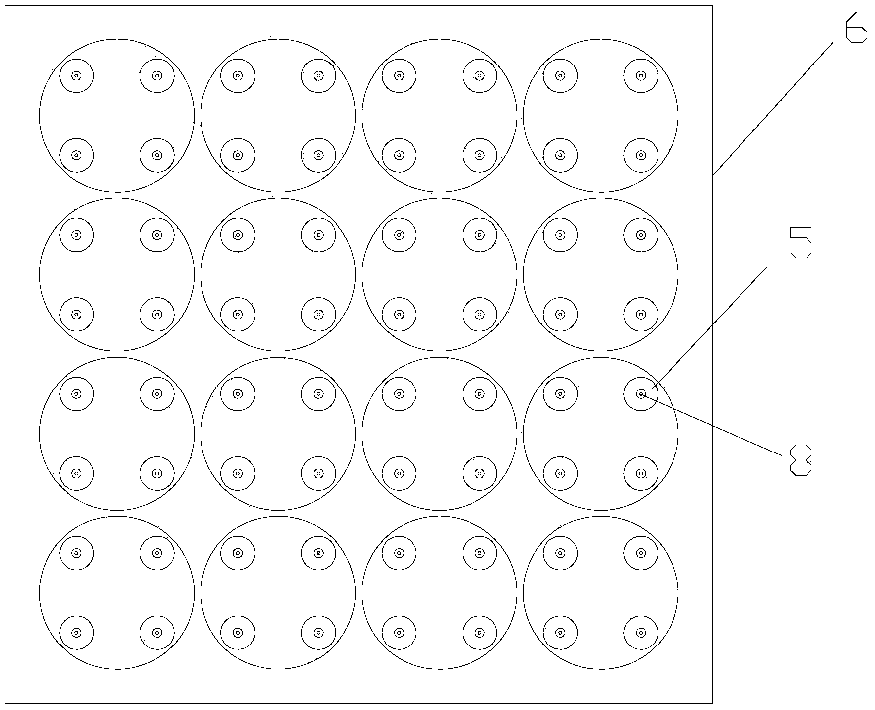
[0014] see figure 1 and 2 , the embodiment of the present invention is provided with a controllable injection device 1, a liquid conduit 2, a liquid separation device 3, a high-voltage power supply 4, an upper air hood 5, a lower air hood 6, a curved electrode plate 7, a spinning nozzle 8, an adapter 9, The lower gas conduit 10 , the auxiliary pressure regulating valve 11 , the auxiliary gas pump 12 , the upper gas conduit 13 , the pressure regulating valve 14 , the gas pump 15 and the receiving device 16 .

[0015] The controllable injection device 1 is connected to one end of the liquid conduit 2, and the other end of the liquid conduit 2 is connected to the infusion port of the liquid dispensing device 3; The boss is connected with the conical inner hole of the spinneret 8; the spinneret 8 passes through the through hole on the curved electrode plate...


PUM


Abstract

The invention provides a multi-spray-head electrostatic spinning device, and relates to an electrostatic spinning device. The multi-spray-head electrostatic spinning device is provided with a controllable injection device, a liquid guide pipe, a liquid distribution device, a high-voltage power supply, an upper layer gas hood, a lower layer gas hood, a curved surface electrode plate, spinning spray heads, an adapter, a lower layer gas guide pipe, an auxiliary pressure regulating valve, an auxiliary gas pump, an upper layer gas guide pipe, a pressure regulating valve, a gas pump and a receiving device. The batch continuous spinning is carried out through the spray heads, double layers of auxiliary gas flows are introduced, the electrostatic spinning speed is accelerated through the drawing force of the upper layer of auxiliary gas flows, the electrostatic spinning efficiency is improved, the nanometer fiber is refined, and the electro-spinning nanometer fiber diameter is reduced. The uniform distribution of the electro-spinning nanometer fiber on a collecting plate is promoted through the lower layer of auxiliary gas flows, the thickness uniformity of a nanometer fiber membrane is improved, the quality of the electrostatic spinning nanometer fiber is improved, charges at the jet flow surface can be carried away, the surface charge density is reduced, and the electrostatic interference among the jet flows is reduced. The electric field concentration phenomenon and the electrostatic interference can be reduced, the spray heads are convenient to dismount, clean and replace, and the operation and the control are easy.

Description

technical field [0001] The invention relates to an electrostatic spinning device, in particular to a multi-nozzle electrostatic spinning device with a large area and multiple jets of double-layer auxiliary gas. Background technique [0002] In recent years, high-voltage electrospinning technology has become the mainstream technology for the preparation of nanofiber materials due to its simplicity, versatility, easy manipulation, and low cost. Nanofibrous materials prepared by electrospinning technology have been widely studied and applied in textiles, filters, reinforcement materials, optoelectronic devices, catalysts, sensors, and biomedicine. At present, traditional electrospinning can only generate one jet with a single spinneret, and the output is only 0.02g / h (O.O.Dosunmu, G.G.Chase, W.Kataphinan and D.H.Reneker. Electrospinning of Polymer Nanofibers from Multiple Jets on a Porous Tubular Surface [J]. Nanotechnology, 2006, 17: 1123-1127), the efficiency is very low, an...

Claims


Application Information

Patent Timeline
IPC IPC(8): D01D5/00
Inventor 郑高峰陈冬阳白鹏王霖洁黄伟伟孙道恒
Owner XIAMEN UNIV
Learn More