
An automatic loading and unloading device

An automatic technology of loading and unloading, applied in the direction of mold separation device, unloading device, mold, etc., can solve the problems of not being able to demould multiple bricks as a whole, reducing production efficiency, and being scratched or damaged greatly. Improve labor productivity, reduce defective products, and reduce demolding resistance

Inactive Publication Date: 2015-12-30
钟赖安
View PDF8 Cites 0 Cited by
  • Summary
  • Abstract
  • Description
  • Claims
  • Application Information

AI Technical Summary

Problems solved by technology

[0002] In the prior art, the mold structures used in the production of bricks or bricks are various, and the required mold device structure is also different in operation procedures, but the brick molds of the prior art basically have the disadvantage that they cannot be demolded at one time or are easy to remove. Defects such as demoulding, low production efficiency, and greater scratching or damage to the formed bricks after demoulding, especially the cumbersome demoulding process has a greater impact on low production efficiency, and the demoulding of brick molds in the prior art Generally, the mold can only demould a single brick alone, and cannot demould multiple bricks (such as ten or dozens) as a whole, which naturally reduces its production efficiency
What's more, there are more processes and lower efficiency when demoulding bricks with various shapes

Method used


Image

  • An automatic loading and unloading device
  • An automatic loading and unloading device
  • An automatic loading and unloading device

Examples


Embodiment 1

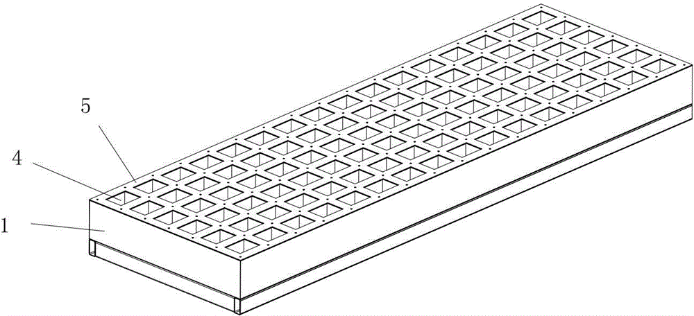
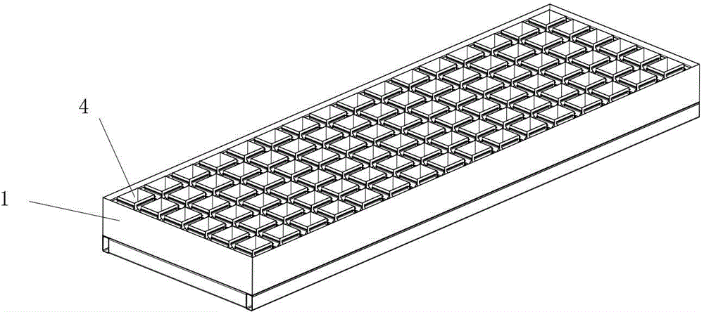
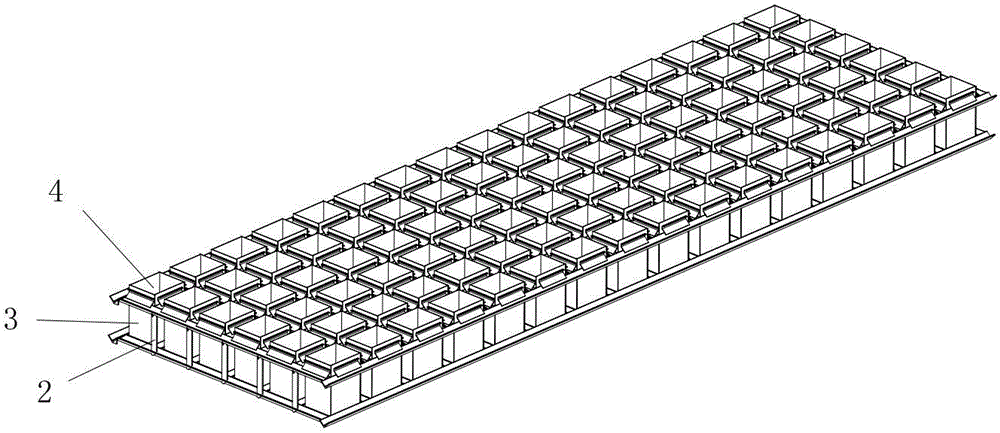
[0022] A kind of automatic loading and unloading device described in this embodiment 1, such as figure 1 , figure 2 , image 3 , Figure 4 , Figure 5 , Image 6 As shown, including a frame 1, a formed keel frame 2 is provided in the frame, a rectangular mold cavity 4 assembled from four movable templates 3 is arranged in the keel frame, and a pressing block 5 and an elastic frame are arranged on the top of the keel frame. Pad 6, the keel frame is provided with a positioning inclined guide groove 7 inwardly and upwardly inclined near the upper end, and a bead 8 with a corresponding angle is provided near the bottom of the keel frame; The guide groove cooperates with the sliding limit guide block 9 which forms a corresponding angle with it, and the movable formwork is provided with a positioning pad 10 which cooperates with the bead and forms a corresponding angle with it near the bottom. During production, the entire automatic loading and unloading device is placed on a ...


PUM


Abstract

The invention discloses an automatic die-filling and die-stripping device, which comprises a framework, wherein a molded skeleton is arranged in the framework, a die cavity which is formed by splicing at least two movable templates is arranged in the skeleton, the top of the skeleton is provided with a pressure block and a resilient cushion block, the position, adjacent to the upper end, of the skeleton is provided with a positioning oblique guide groove which is inclined inwards and upwards, the position, adjacent to the bottom, of the skeleton is provided with a depression bar with a corresponding angle; the position, adjacent to the upper end, of the movable template is provided with a sliding limiting guide block which is matched with the positioning oblique guide groove; a corresponding angle is formed between sliding limiting guide block and the positioning oblique guide groove, and the position, adjacent to the bottom, of the movable template is provided with a positioning cushion block which is matched with the depression bar; and a corresponding angle is formed between positioning cushion block and the depression bar. By adopting the automatic die-filling and die-stripping device, multiple concrete prefabricated members can be produced in one step and integrally demoulded in one step. The automatic die-filling and die-stripping device is simple in structure, the machine is used for substituting the manual steps for installing the die, stripping the die and the like, the labor production efficiency can be greatly improved, the completeness of the concrete prefabricated member can be guaranteed, the rejected products can be reduced, and the labor intensity of workers can be alleviated.

Description

technical field [0001] The present invention relates to the technical field of an automatic loading and unloading device, in particular to a positioning sliding mechanism set on a keel, a sliding and hanging mechanism for a movable formwork, which can realize self-demolding, automatic mold loading by using the mold's own weight, simple and convenient brick and Block mold device. Background technique [0002] In the prior art, the mold structures used in the production of bricks or bricks are various, and the required mold device structure is also different in operation procedures, but the brick molds of the prior art basically have the disadvantage that they cannot be demolded at one time or are easy to remove. Defects such as demoulding, low production efficiency, and greater scratching or damage to the formed bricks after demoulding, especially the cumbersome demoulding process has a greater impact on low production efficiency, and the demoulding of brick molds in the prio...

Claims


Application Information

Patent Timeline
Patent Type & Authority Patents(China)
IPC IPC(8): B28B7/26B28B13/06
CPCB28B7/10
Inventor 钟赖安
Owner 钟赖安
Learn More