High-power sputtering source

A power and power supply technology, applied in sputtering coating, vacuum evaporation coating, coating and other directions, which can solve the problems of poor target utilization, distribution, and high cost.

Active Publication Date: 2014-03-05
OERLIKON SURFACE SOLUTIONS AG PFAFFIKON
View PDF6 Cites 3 Cited by
  • Summary
  • Abstract
  • Description
  • Claims
  • Application Information

AI Technical Summary

Problems solved by technology

[0011] A disadvantage of the device of Nyberg et al. is the fact that such a configuration cannot be operated in conventional magnetron sputtering mode, since it is not possible or technically very costly to distribute the power of one generator evenly over the different parts
Disadvantages of the solution of Nyberg et al. are also, inter alia, the resulting fixed erosion grooves on each of the part targets that can be switched on or off
This means that target utilization is significantly worse compared to the rotating magnetron described by Wang et al.

Method used


Image

  • High-power sputtering source
  • High-power sputtering source
  • High-power sputtering source

Examples


Embodiment Construction

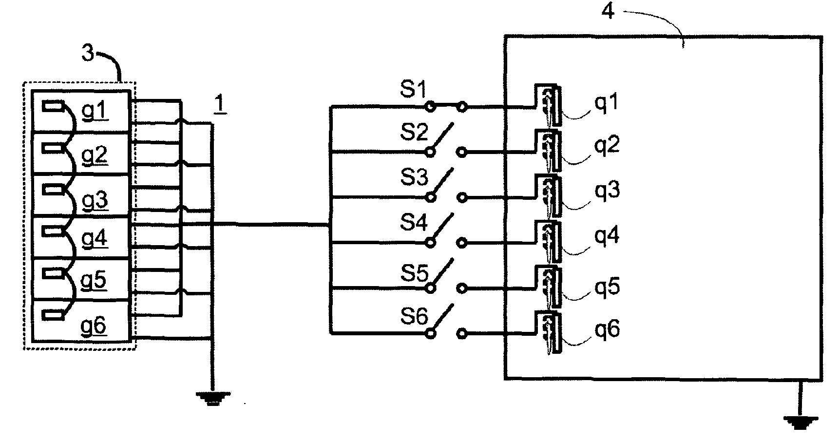
[0022] According to the first embodiment of the present invention, such as figure 2 As exemplarily shown in , the power supply unit 3 supplies voltage and current to the sputtering source q1 arranged in the vacuum chamber 4 via the switch S1 for operating the sputtering device in HIPIMS mode. The power supply unit 3 consists of a plurality of generators g1 to g6 connected in a master-slave configuration. They can be designed as DC generators, pulsed DC generators. The sputtering source q1 is designed as a magnetron sputtering source with a partial target, wherein according to a preferred variant of this embodiment, a movable, preferably rotatably mounted, magnet system is arranged behind the partial target of the sputtering source q1 msl. In application, the trajectory is moved over almost the entire surface of the target of the sputtering source q1 by movement, preferably rotation, of the magnetic system ms1.

[0023] Feed rare gas and / or reactive gas, such as N in the va...


PUM


Abstract

The invention relates to a magnetron sputtering process that allows material to be sputtered from a target surface in such a way that a high percentage of the sputtered material is provided in the form of ions. According to the invention, said aim is achieved using a simple generator, the power of which is fed to multiple magnetron sputtering sources spread out over several time intervals, i.e. the maximum power is supplied to one sputtering source during one time interval, and the maximum power is supplied to the following sputtering source in the subsequent time interval, such that discharge current densities of more than 0.2A / cm2 are obtained. The sputtering target can cool down during the off time, thus preventing the temperature limit from being exceeded.

Description

technical field [0001] The invention relates to a method for coating a substrate by means of magnetron sputtering. Background technique [0002] Within the scope of this description, "sputtering" and "sputtering" are used synonymously. [0003] In the case of sputtering, the target (cathode) is bombarded with ions, which causes the material of the target to be eroded. The ions are accelerated in the direction of the target surface formed by the plasma by means of an electric field. In the case of magnetron sputtering, a magnetic field is constructed on the target surface. In this way, the electrons in the plasma are forced into helical trajectories and circle the target surface. Over their extended path, the number of collisions of electrons with atoms or ions increases significantly, which leads to a higher ionization in this region on the target surface. This results in increased sputter attack on the target directly below this region. This results in an erosion trenc...

Claims


Application Information

Patent Timeline
IPC IPC(8): H01J37/34C23C14/34
CPCH01J37/3464H01J37/3444C23C14/352H01J37/3497C23C14/35H01J37/3405H01J37/3467C23C14/34H01J37/34C23C14/54
Inventor S.克拉斯尼策尔K.鲁姆
Owner OERLIKON SURFACE SOLUTIONS AG PFAFFIKON
Why Eureka
Try Eureka