Automatic grease discharging structure of motor rolling bearing

A technology of rolling bearings and automatic discharge, which is applied in the direction of electric components, casings/covers/supports, electrical components, etc., can solve the problems of reducing motor efficiency, consuming electric energy, and high frictional heat generation between grease disc and grease, etc., to achieve Strengthen the convection heat dissipation capacity, ensure safe and reliable operation, and improve the effect of lubrication reliability

Active Publication Date: 2014-03-05
武汉奥特彼电机有限公司
View PDF5 Cites 6 Cited by
  • Summary
  • Abstract
  • Description
  • Claims
  • Application Information

AI Technical Summary

Problems solved by technology

In the grease discharge structure of the grease removal plate, there is too much heat generated by the friction between the grease removal plate and the grease, which in turn causes the working temperature of the bearing to be too high
In the non-grease structure, because the grease cannot be discharged from the bearing under the action of external force, there is too much grease in the cavity of the bearing chamber, and there is a thick layer of grease between the outer end surface of the bearing and the outer cover of the bearing, resulting in the failure of the bearing to dissipate heat. Bearing operating temperature is too high
Both of these two structures will cause high operating temperature of the bearing and poor operating reliability of the bearing; additional friction loss of the bearing will reduce the efficiency of the motor and consume a lot of electric energy, and the grease must be manually discharged. Manual degreasing will cause too much grease in the cavity of the bearing chamber, further increase the bearing friction, further increase the bearing temperature, the manual degreasing operation is complicated, the labor intensity of the field equipment maintenance personnel is high, and it is difficult to improve the automation degree of the motor

Method used


Image

  • Automatic grease discharging structure of motor rolling bearing
  • Automatic grease discharging structure of motor rolling bearing
  • Automatic grease discharging structure of motor rolling bearing

Examples


Embodiment Construction

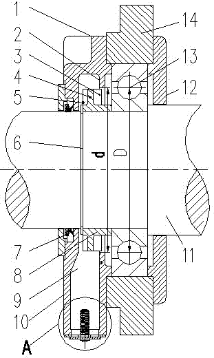
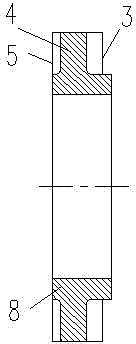
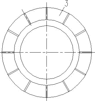
[0023] Depend on Figure 1-Figure 5 The automatic degreasing structure of the motor rolling bearing shown includes a rotating shaft 11, on which a bearing front cover 1, a bearing 13 and a bearing rear cover 12 are arranged in sequence from front to back, the bearing 13 is arranged in a bearing seat 14, and the bearing seat 14 is located between the bearing front cover 1 and the bearing rear cover 12. The bearing front cover 1 includes a radial cover plate 10 and a side plate arranged around the rear side of the outer edge of the cover plate 10. The rotating shaft 11 and the bearing front cover 1, the rotating shaft 11 and the The bearing back cover 12 is all plugged in, and a shaft penetration sealing structure is provided between the bearing front cover 1 and the rotating shaft 11. The bearing front cover 1, the bearing seat 14 and the bearing back cover 12 are fixedly connected by bolts. The bearing front cover 1, The connecting structure of the bearing block 14 and the bea...


PUM


Abstract

The invention discloses an automatic grease discharging structure of a motor rolling bearing. The automatic grease discharging structure comprises a rotating shaft. A bearing front cover, the bearing and a bearing rear cover are sequentially arranged on the rotating shaft. The bearing is arranged inside a bearing pedestal. The portion, inside the bearing front cover, of the rotating shaft is sleeved with a centrifugal grease throwing ring which can rotate along with the rotating shaft. The two end faces of the centrifugal grease throwing ring are respectively provided with a rear centrifugal blade which faces towards the bearing. An annular grease blocking weir plate is arranged inside the bearing front cover. The grease blocking weir plate and the bearing are arranged in a spaced mode. Each rear centrifugal blade backward extends from the front side of the grease blocking weir plate into an annular hole of the grease blocking weir plate. Grease discharging holes are formed in the portion, on the radial side of the centrifugal blades, of the bearing front cover, and the grease discharging holes are located in the front side of the grease blocking weir plate. An automatic grease discharging valve with a compression spring is arranged below the grease discharging holes. The automatic grease discharging structure overcomes the defects of an existing grease throwing plate grease discharging structure and an existing non-grease-discharging structure of a rolling bearing, and is simple in structure, good in heat dissipation performance, good in sealing performance and high in use and maintenance automation degree.

Description

technical field [0001] The invention belongs to the improvement technology of motor bearings, and in particular relates to an automatic grease-discharging structure of motor rolling bearings. Background technique [0002] Rolling bearing is a precision mechanical element that changes the sliding friction between the running shaft and the shaft seat into rolling friction, thereby reducing friction loss. The lubrication reliability of the bearing and the operating temperature have a great influence on the working performance of the bearing. At present, rolling bearings usually adopt a grease-discharging structure and a non-grease-discharging structure. In the grease discharge structure of the grease removal plate, there is too much heat generated by the friction between the grease removal plate and the grease, which in turn causes the working temperature of the bearing to be too high. In the non-grease structure, because the grease cannot be discharged from the bearing under ...

Claims


Application Information

Patent Timeline
IPC IPC(8): H02K5/173H02K9/06H02K5/10
Inventor 张运生吴宣东乔建伟曲振业陈建军徐元周张磊赵强
Owner 武汉奥特彼电机有限公司
Why Eureka
Try Eureka