Broadband Miniaturized Radiating Unit and Its Base Station Antenna

A radiation unit and broadband technology, applied in the field of broadband miniaturized radiation unit and its base station antenna, can solve the deterioration of high frequency unit pattern performance and circuit performance, increase the complexity and cost of the antenna, and the lack of a reasonable layout of the radiation arm, etc. problems, to achieve the effect of improving circuit and pattern performance, improving circuit performance and pattern performance, and saving materials

Active Publication Date: 2017-05-24
GCI SCI & TECH
View PDF9 Cites 0 Cited by
  • Summary
  • Abstract
  • Description
  • Claims
  • Application Information

AI Technical Summary

Problems solved by technology

The low-frequency radiation unit obviously blocks the high-frequency radiation unit in the middle, which seriously deteriorates the performance of the high-frequency unit’s directional diagram and circuit performance, and further reduces the performance of the whole machine. In the actual antenna, a complex plastic medium has to be added above the vibrator to reduce Severe mutual coupling between frequency bands, but this also increases the complexity and cost of the antenna
[0010] Both the CN201134512Y patent and the CN201820883U patent have improved the above unit forms, mainly by bending the original straight radiation arm so that the front projection is circular or octagonal, which reduces the impact of the low-frequency radiation unit to a certain extent. The influence of the high-frequency radiation unit between the two low-frequency radiation units, but when coaxial with the LTE ultra-wideband high-frequency unit (working frequency: 1710-2690MHz), the wavelength corresponding to the 2690MHz frequency point is only 111mm , in order to take into account the performance of the high-frequency pattern, when the array spacing of the low-frequency radiating units is further reduced, the same problem will still occur
The reason is that the radiation arms of the radiation unit are not properly arranged, resulting in serious mutual coupling problems under a small array spacing

Method used


Image

  • Broadband Miniaturized Radiating Unit and Its Base Station Antenna
  • Broadband Miniaturized Radiating Unit and Its Base Station Antenna
  • Broadband Miniaturized Radiating Unit and Its Base Station Antenna

Examples


Embodiment Construction

[0048] In order to make the object, technical solution and advantages of the present invention clearer, the present invention will be further described in detail below in conjunction with the accompanying drawings.

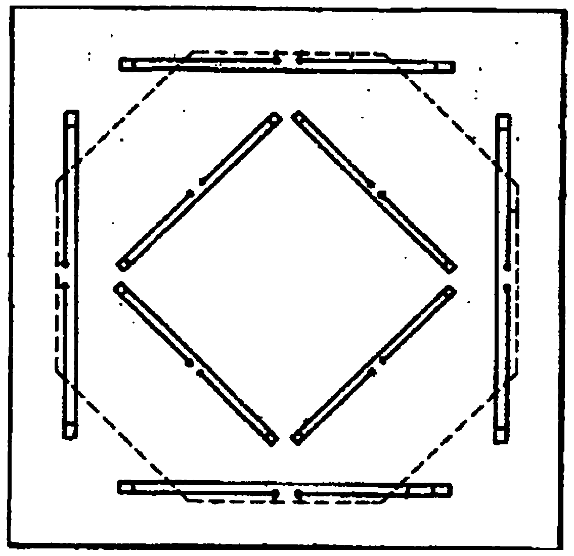
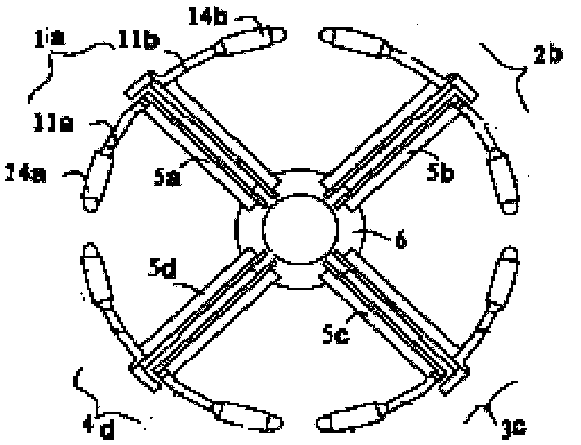
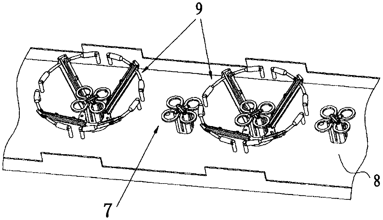
[0049] The overall structure model of the wide-band miniaturized radiation unit of the embodiment of the present invention is as follows Figure 8 to Figure 10 shown. Figure 8 It is a schematic diagram of the orthographic projection of the radiation unit embodiment of the present invention, Figure 9 It is a side projection schematic diagram of an embodiment of the radiation unit of the present invention, Figure 10 It is a three-dimensional schematic diagram of an embodiment of the radiation unit of the present invention. like Figure 8 As shown, the broadband miniaturized radiation unit of this embodiment includes a base 1, four baluns 2A, 2B, 2C, 2D and four half-wave oscillators 3A, 3B, 3C, 3D. The structure of the base 1 can be a quadrilateral, polygonal...


PUM


Abstract

The embodiment of the invention discloses a broadband miniaturization radiating element which comprises two pairs of cross polarization half-wave vibrators, four Baluns and a base, the cross polarization half-wave vibrators are used for sending or receiving signals in the wireless communication process, one end of each Balun is correspondingly connected with one half-wave vibrator, the other end of each Balun is connected with the base, each half-wave vibrator comprises two radiating arms, and each radiating arm comprises a first radiating section, a second radiating section and an internal connecting section used for being connected with the first radiating section and the second radiating section. In the projection of the plane where the base is located, the second radiating sections are contracted towards the center of the radiating element relative to the first radiating sections. The embodiment of the invention further discloses a base station antenna formed by the broadband miniaturization radiating element. Through the broadband miniaturization radiating element and the base station antenna, the overall dimension can be effectively reduced, and the overall radiating element is miniaturized. The radiating element has obvious advantages under the condition of small-distance set arrays.

Description

technical field [0001] The invention relates to the field of mobile communication base station antennas, in particular to a broadband miniaturized radiation unit and a base station antenna. Background technique [0002] The plate-shaped directional array antenna can achieve a complex overall pattern through the change of the amplitude and phase of the feeding of each radiating element and the change of the boundary of the reflector, thereby achieving good area coverage. Taking the single-band array antenna as an example, in order to achieve higher gain, the array spacing between array elements is usually 0.8-1 wavelength of the center frequency point. If the array spacing is too small, the combined gain will not be high. Too large will lead to the appearance of grating lobes, especially in the case of more and more high-rise buildings and smaller and smaller mobile cells, antennas with large downtilt angles are often required, and the influence of array spacing on grating lo...

Claims


Application Information

Patent Timeline
Patent Type & Authority Patents(China)
IPC IPC(8): H01Q1/36H01Q1/52H01Q1/50H01Q19/10H01Q21/24H01Q21/30
Inventor 郑春暖陈韶明孙亚波
Owner GCI SCI & TECH
Why Eureka
Try Eureka