
A vehicle remote diagnosis system and diagnosis method

A remote diagnosis and vehicle technology, applied in the field of vehicle remote diagnosis system, can solve problems such as inconvenient installation of diagnostic equipment and display screens, lower market competitiveness of complete vehicles, and high cost of diagnostic equipment, and achieve simple and easy diagnostic operations and improved Market competitiveness and the effect of reducing diagnostic costs

Active Publication Date: 2016-08-17
CHERY AUTOMOBILE CO LTD
View PDF6 Cites 0 Cited by
  • Summary
  • Abstract
  • Description
  • Claims
  • Application Information

AI Technical Summary

Problems solved by technology

Another type of vehicle diagnostic technology is the Internet-based remote diagnostic technology developed in recent years. This diagnostic technology realizes vehicle diagnostics by configuring relevant diagnostic equipment inside the vehicle and sending diagnostic data to a remote terminal through a wireless network. Diagnostic function, this kind of specially equipped diagnostic equipment is expensive, and it needs to be specially equipped with a diagnostic display screen for this diagnostic equipment, which makes it extremely inconvenient to install the diagnostic equipment and display screen under the condition of limited space in the car, and additional diagnostic equipment Equipment and display screens will lead to an increase in the overall price of the vehicle, reducing the market competitiveness of the vehicle. In addition, various Internet-based vehicle diagnostic technologies in the prior art still have shortcomings such as unstable diagnostic performance and incomplete diagnostic functions.

Method used


Image

  • A vehicle remote diagnosis system and diagnosis method
  • A vehicle remote diagnosis system and diagnosis method
  • A vehicle remote diagnosis system and diagnosis method

Examples


Embodiment Construction

[0040] The technical solution of the present invention will be described in detail below in conjunction with the accompanying drawings, so that those skilled in the art can understand the solution of the present invention more clearly, but the protection scope of the present invention is not limited thereby.

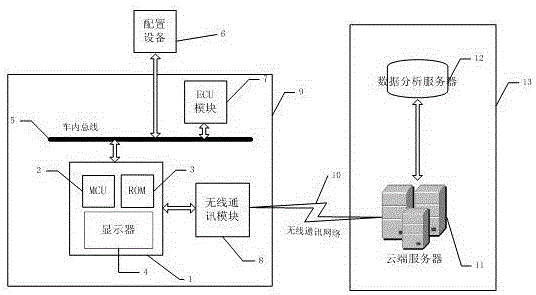
[0041] attached figure 1 A schematic diagram of the overall composition and structure of the vehicle remote diagnosis system of the present invention is given, as shown in the attached figure 1As shown, the vehicle remote diagnosis system of the present invention as a whole includes a configuration device 6 , an in-vehicle diagnosis unit 9 and a remote diagnosis unit 13 , and the in-vehicle diagnosis unit 9 and the remote diagnosis unit 13 are connected through a wireless communication network 10 . The in-vehicle diagnostic unit 9 specifically includes an in-vehicle infotainment system 1 , an in-vehicle bus 5 , an ECU module 7 and a wireless communication module 8 , wher...


PUM


Abstract

The present invention proposes a vehicle remote diagnosis system and diagnosis method. The system includes a configuration device, an in-vehicle diagnosis unit and a remote diagnosis unit. The in-vehicle diagnosis unit and the remote diagnosis unit are connected through a wireless communication network. Entertainment system, in-vehicle bus and wireless communication module, the configuration equipment is connected to the vehicle infotainment system through the vehicle bus, and the vehicle infotainment system is used to receive user diagnostic commands, collect diagnostic data and send diagnostic data to the remote diagnostic unit through the wireless communication module package, and at the same time receive and display the diagnosis result data sent back by the wireless communication module. The present invention avoids the equipment and installation of separate diagnostic equipment by integrating the diagnostic module into the necessary vehicle infotainment system of the vehicle, and reduces the cost of the whole vehicle. The diagnosis can be realized by simple operation on the vehicle infotainment system , reducing the professional requirements of vehicle diagnosis, while greatly improving the performance and efficiency of remote diagnosis.

Description

technical field [0001] The invention relates to the technical field of vehicle fault diagnosis, and more specifically relates to a vehicle remote diagnosis system and a diagnosis method. Background technique [0002] Vehicle diagnostic technologies in the prior art are generally divided into two categories: one is to use a diagnostic instrument to connect to the vehicle's internal bus, read the ECU module fault code in the vehicle, and then perform vehicle fault diagnosis based on the diagnostic instrument and related equipment. This diagnosis method needs to drive the vehicle to a specific place for implementation, and requires specialized personnel to operate, which is relatively professional. In the prior art, most vehicles go to 4S stores for detection and diagnosis. Another type of vehicle diagnostic technology is the Internet-based remote diagnostic technology developed in recent years. This diagnostic technology realizes vehicle diagnostics by configuring relevant dia...

Claims


Application Information

Patent Timeline
Patent Type & Authority Patents(China)
IPC IPC(8): G01M17/007
Inventor 尚云飞张圣峰陈福全赵松岭胡红星
Owner CHERY AUTOMOBILE CO LTD
Learn More