Seed injection BOTDR distributed optical fiber sensing system
A distributed optical fiber, sensing system technology, applied in the direction of using optical devices to transmit sensing components, etc., can solve the problems of short sensing distance, difficult fault detection, low signal-to-noise ratio of BOTDR system, and achieve simple structure, sensing The effect of stable signal output and improved signal-to-noise ratio
- Summary
- Abstract
- Description
- Claims
- Application Information
AI Technical Summary
Problems solved by technology
Method used
Image

Examples
specific Embodiment approach 1
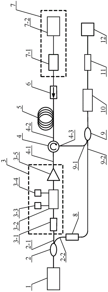
[0016] Specific implementation mode one: combine figure 1 Describe this embodiment, the seed injection BOTDR distributed optical fiber sensing system described in this embodiment includes a narrowband fiber laser 1, a first fiber coupler 2, a pump optical module 3, a fiber circulator 4, a sensing fiber 5, an optical fiber Isolator 6, seed optical module 7, polarization controller 8, second fiber coupler 9, photodetector 10 and microwave down-conversion module 11, the output end of the narrowband fiber laser 1 is connected to the input of the first fiber coupler 2 end, the first output port 2-1 of the first optical fiber coupler 2 is connected to the input end of the pumping optical module 3, and the output end of the pumping optical module 3 is connected to the first port 4-1 of the optical fiber circulator 4, and the optical fiber The second port 4-2 of the circulator 4 is connected to one end of the sensing fiber 5, the laser light output by the seed optical module 7 enters ...
specific Embodiment approach 2
[0019] Specific implementation mode two: combination figure 1 Describe this embodiment, this embodiment is a further limitation of the seed injection BOTDR distributed optical fiber sensing system described in Embodiment 1: the pump optical module 3 includes a polarization controller 3-1, an intensity modulator 3- 2. DC stabilized power supply 3-3, arbitrary waveform signal generator 3-4 and erbium-doped fiber amplifier 3-5, the optical fiber input end of the polarization controller 3-1 is connected to the first output of the first optical fiber coupler 2 Port 2-1, the output end of the polarization controller 3-1 is connected to the optical input end of the intensity modulator 3-2, and the optical output end of the intensity modulator 3-2 is connected to the seed optical input of the erbium-doped fiber amplifier 3-5 end, the output end of the erbium-doped fiber amplifier 3-5 is the output end of the pump optical module 3, the electrical signal output end of the DC stabilized ...
specific Embodiment approach 3
[0020] Specific implementation mode three: combination figure 1Describe this embodiment, this embodiment is a further limitation of the seed injection BOTDR distributed optical fiber sensing system described in Embodiment 1: the seed optical module 7 includes a fiber filter 7-1 and a broadband light source 7-2, The laser output from the broadband light source 7-2 enters the fiber isolator 6 after passing through the fiber filter 7-1.
PUM
| Property | Measurement | Unit |
|---|---|---|
| Bandwidth | aaaaa | aaaaa |
| Bandwidth | aaaaa | aaaaa |
| Bandwidth | aaaaa | aaaaa |
Abstract
Description
Claims
Application Information
 - R&D
- Intellectual Property
- Life Sciences
- Materials
- Tech Scout
- Unparalleled Data Quality
- Higher Quality Content
- 60% Fewer Hallucinations
Browse by: Latest US Patents, China's latest patents, Technical Efficacy Thesaurus, Application Domain, Technology Topic, Popular Technical Reports.
© 2025 PatSnap. All rights reserved.Legal|Privacy policy|Modern Slavery Act Transparency Statement|Sitemap|About US| Contact US: help@patsnap.com