
High altitude spherical net rack splicing method based on large gymnasium frame continuous beam

A network frame and ball-shaped technology, which is applied in the field of high-altitude ball-shaped network frame splicing, can solve the problems of large site, long construction period, and affecting the simultaneous construction of the lower part of the network frame, so as to shorten the construction period, occupy a small space on the site, and shorten the overall The effect of duration

Inactive Publication Date: 2014-02-26
MCC TIANGONG GROUP
View PDF5 Cites 7 Cited by
  • Summary
  • Abstract
  • Description
  • Claims
  • Application Information

AI Technical Summary

Problems solved by technology

During the hoisting process, the lower part of the network frame will be affected by the hoisting and needs to be constructed later, so that the construction period will be extended accordingly; there is also a common sliding construction method, which is carried out by laying fixed tracks on the ground, which requires a large space. And it will affect the synchronous construction of the lower part of the network frame

Method used


Image

  • High altitude spherical net rack splicing method based on large gymnasium frame continuous beam
  • High altitude spherical net rack splicing method based on large gymnasium frame continuous beam
  • High altitude spherical net rack splicing method based on large gymnasium frame continuous beam

Examples


Embodiment Construction

[0022] The present invention will be further described in detail below through the specific examples, the following examples are only descriptive, not restrictive, and cannot limit the protection scope of the present invention with this.

[0023] A high-altitude spherical grid splicing method based on the continuous beam of the frame of a large venue, the steps are as follows:

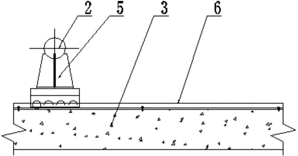
[0024] (1) Build the left installation platform 1 and the right installation platform 4 under the two ends of the continuous beam 3 of the frame of the large venue respectively;

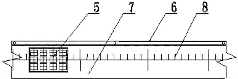
[0025] (2) Install the slideway 7 on the continuous beam of the frame of the large-scale venue, and slide and install the moving trolley 5 of the grid frame at both ends of the slideway; pop up the deflection correction axis 8 of the grid sliding track on the continuous beam of the large-scale venue frame; The side-slip limiting angle steel 6 is respectively fixed on the continuous beams of the large venue frame on both sides...


PUM


Abstract

The invention relates to a high altitude spherical net rack splicing method based on a large gymnasium frame continuous beam. The method includes the following steps: (1) building a left installation platform and a right installation platform under two ends of the large gymnasium frame continuous beam respectively; (2) installing a slide on the large gymnasium frame continuous beam and installing net rack moving trolleys at two ends of the slide in a sliding mode; (3) dividing a high altitude spherical net rack into N sections with the length being N meters and obtained through calculation; (4) splicing an L-meter high altitude spherical net rack and erecting the net rack on the net rack moving trolleys; (5) utilizing a drawing device to draw the net rack moving trolleys to enable the L-meter high altitude spherical net rack to move forward for L meters relatively and respectively and repeating the steps to assemble the whole high altitude spherical net rack in a splicing mode to finish the splicing. The net rack splicing method can shorten construction time, a sliding moving system is simple to machine and manufacture, sliding moving operation is high in speed, occupied space is small, labor intensity of workers is reduced, and the construction period is shortened.

Description

technical field [0001] The invention belongs to the field of spherical grid construction, in particular to a high-altitude spherical grid splicing method based on continuous beams of large stadium frames. Background technique [0002] In the field of roof grid construction, the method of hoisting spherical grids by cranes is very common. During the hoisting process, the lower part of the grid structure will be affected by the hoisting and needs to be constructed later, so that the construction period will be extended accordingly; there is also a common sliding construction method, which is carried out by laying fixed rails on the ground, which requires a large space. And it will affect the synchronous construction of the lower part of the grid. Contents of the invention [0003] The purpose of the present invention is to overcome the difficulty of cross-joint work under the premise of tight construction schedule, and provide a high-altitude spherical grid splicing method ...

Claims


Application Information

Patent Timeline
Patent Type & Authority Applications(China)
IPC IPC(8): E04G21/14
Inventor 崔健成永旭陈福平贾金现余永拴
Owner MCC TIANGONG GROUP
Learn More