
Rotary guide shoe

A technology of guiding shoes and swivel seats, which is applied in the direction of drilling equipment, earthwork drilling, drill pipes, etc., and can solve the problems of not being able to reduce casing resistance, affecting cementing quality, and having no rotatable structure, etc.

Active Publication Date: 2014-02-19
CHANGQING GUJING OF CNPC CHUANQING DRILLING ENG
View PDF7 Cites 6 Cited by
  • Summary
  • Abstract
  • Description
  • Claims
  • Application Information

AI Technical Summary

Problems solved by technology

[0002] In the prior art, the front end of the casing string used for cementing operations has no rotatable structure, and the outer diameter of the casing string is the same as that of the casing. Drilling fluid cannot play the role of flushing the well wall, which in turn affects the running speed of the casing and affects the cementing quality

Method used


Image

  • Rotary guide shoe
  • Rotary guide shoe
  • Rotary guide shoe

Examples


Embodiment 1

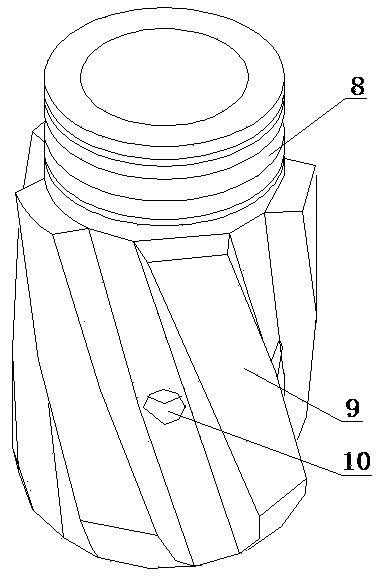
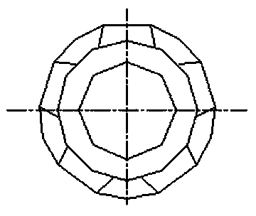
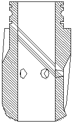
[0018] Such as figure 1 , figure 2 , image 3 , Figure 4 , Figure 5 , Image 6 and Figure 7 The shown rotating shoe includes a rotating base 1 and a guiding end 2 arranged at the lower end of the rotating base 1. The guiding end 2 is a hollow structure, and its outer surface is provided with a plurality of blades 9 inclined from top to bottom. A discharge hole 10 leading to the inside of the guide end 2 is provided between adjacent blades 9; a rotating turbine blade 5 connected through a blade seat 13 is provided inside the guide end 2; the blade seat 13 is arranged on the top of the guide end 2; The center of the blade base 13 is provided with a central hole, and the bottom surface of the blade base 13 is provided with a hollow column coaxial with the central hole. There are at least three rotating turbine blades 5, and the inner ends of the rotating turbine blades 5 are connected to the The hollow column is connected, and the top of the rotating turbine blade 5 is ...

Embodiment 2

[0020] On the basis of Embodiment 1, the blade seat 13 is integrally formed with the leading end 2 or connected through threads. The inner wall of the lower end of the rotating seat 1 is provided with a first ball groove 7, the outer wall of the upper end of the leading end 2 is provided with a second ball groove 8 matching the first ball groove 7, and the surface of the rotating seat 1 is provided with a through hole. Assembly holes 11 for assembling balls to the first ball groove 7 and the second ball groove 8, the first ball groove 7 and the second ball groove 8 contain a plurality of balls 3, and plugs 6 are installed on the assembly holes; A sealing ring 4 is also provided between 1 and the leading end 2, and the sealing ring 4 is located below the first ball groove 7 and the second ball groove 8.


PUM


Abstract

The invention belongs to the technical field of oil development cementing tools and particularly provides a rotary guide shoe. The drainage rotary guide shoe comprises a rotating base and a guide end arranged at the lower end of the rotating base. The guide end is of a hollow structure, a plurality of blades in the inclined direction from top to bottom are arranged on the outer surface of the guide end, and drainage holes communicated with the inside of the guide end are formed between the adjacent blades. At least three rotating turbine blades connected through a blade base are arranged in the guide end, the blade base is arranged at the top of the guide end, a central hole is formed in the center of the blade base, a hollow column coaxial with the central hole is arranged on the bottom face of the blade base, the inner ends of the rotating turbine blades are connected with the hollow column, and the tops of the rotating turbine blades are connected with the blade base (13). At least three through holes are formed in the periphery of the blade base, and the through holes are respectively formed between the adjacent rotating turbine blades. The rotary guide shoe has rotating and guiding functions and is suitable for being used for special wells with long horizontal sections, stratum collapse and severe hole shrinkage.

Description

technical field [0001] The invention belongs to the technical field of oil development cementing tools, and in particular relates to a rotary guide shoe. Background technique [0002] In the prior art, the front end of the casing string used for cementing operations has no rotatable structure, and the outer diameter of the casing string is the same as that of the casing. Drilling fluid cannot play the role of scouring the well wall, which in turn affects the running speed of the casing and affects the cementing quality. Contents of the invention [0003] The purpose of the present invention is to overcome the deficiencies of the prior art. By adding rotating turbine blades and unloading holes on the pipe wall, the guide shoe has the functions of rotation and guidance, and is suitable for special wells with relatively long horizontal sections, stratum collapse and serious diameter reduction. . [0004] To this end, the present invention provides a rotating guide shoe, whi...

Claims


Application Information

Patent Timeline
Patent Type & Authority Applications(China)
IPC IPC(8): E21B17/14
Inventor 王晓东王大权刘丰克殷其军窦虎清刘健
Owner CHANGQING GUJING OF CNPC CHUANQING DRILLING ENG
Learn More