
Tool clamp for machining cutting edge of workpiece and operation method of tool clamp

A technology for machining workpieces and fixtures. It is used in the control of workpiece feed motion, manufacturing tools, and grinding workpiece supports. It can solve the problem that the workpiece is not easy to reverse, adjust, clamp and locate a single function, and the waste is not easy to centralize processing, etc. It can improve transmission efficiency and transmission accuracy, facilitate collection, and reduce noise and resistance.

Inactive Publication Date: 2021-10-08
龚叶
View PDF1 Cites 0 Cited by
  • Summary
  • Abstract
  • Description
  • Claims
  • Application Information

AI Technical Summary

Problems solved by technology

[0005] In order to solve the above-mentioned technical problems, the present invention provides a tooling fixture for processing the cutting edge of a workpiece and its operation method to solve the problem that when the workpiece processing equipment similar to the above-mentioned patent is used, it is clamped by an external device and has a single clamping and positioning function. , the waste is not easy to concentrate on processing, the workpiece is not easy to change direction and adjust, and it is not convenient for multi-directional processing.

Method used


Image

  • Tool clamp for machining cutting edge of workpiece and operation method of tool clamp
  • Tool clamp for machining cutting edge of workpiece and operation method of tool clamp
  • Tool clamp for machining cutting edge of workpiece and operation method of tool clamp

Examples


Embodiment

[0034] as attached figure 1 To attach Figure 8 Shown:

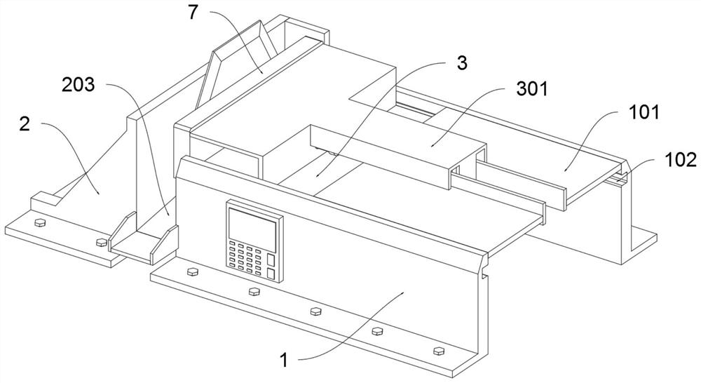
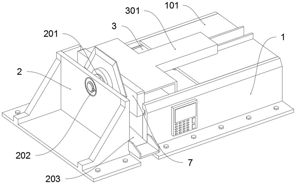
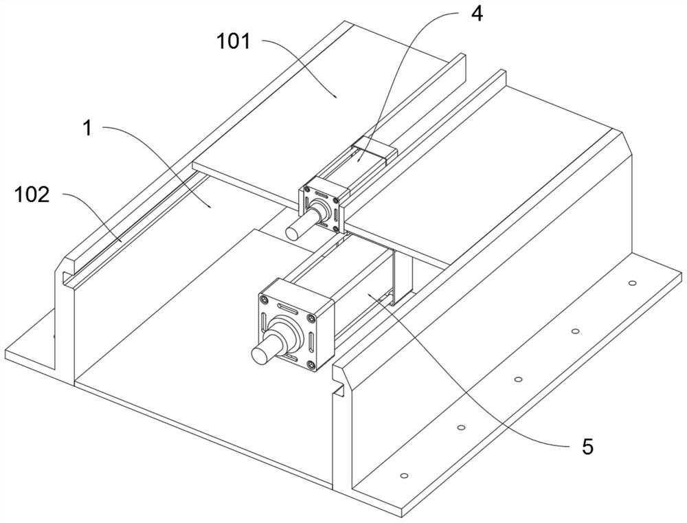
[0035] The present invention provides a tooling fixture for processing workpiece cutting edge and its operation method, which comprises an active clamping table 1; a positioning frame 2 is fixedly connected to the left side of the active clamping table 1; In the middle; the reversing pusher 4 is fixedly connected to the top of the active clamping table 1 by screws; the clamping pusher 5 is fixedly connected to the bottom plate of the active clamping table 1 by screws, and the output rod of the clamping pusher 5 is connected and driven to move The bottom of the push frame 3; the top frame 6 is fixedly connected to the output push rod of the reversing pusher 4; the positioning pressure plate 7 is fixedly connected to the left end of the movable push frame 3; the rotary drive member 8 is fixedly connected to the lower surface of the upper baffle plate 301 , and the rotary drive member 8 is connected and drives the top fra...


PUM


Abstract

The invention provides a tool clamp for machining a cutting edge of a workpiece and an operation method of the tool clamp. The tool clamp comprises a driving clamping table; a positioning frame seat is fixedly connected to the left side of the driving clamping table; a movable pushing frame is connected to the middle of the driving clamping table in a sliding manner; a reversing pushing piece is fixedly connected to the upper portion of the driving clamping table through a screw; a clamping pushing piece is fixedly connected to the upper portion of a bottom plate of the driving clamping table through a screw, and an output rod of the clamping pushing piece is connected with and drives the lower portion of the movable pushing frame; a top frame is fixedly connected to an output push rod of the reversing push piece; a positioning pressing plate is fixedly connected to the left end of the movable pushing frame; and the top frame rotates to control the workpiece to rotate under the action of a positioning chuck, after the adjustment is completed, the clamping pushing piece pushes the movable pushing frame to move leftwards, the positioning pressing plate clamps the workpiece again, meanwhile, a positioning groove is matched with a positioning conical block, the top frame is locked, rotation of the top frame is avoided, multi-direction adjustment conversion of the workpiece is achieved, and machining is facilitated.

Description

technical field [0001] The invention belongs to the technical field of mechanical processing, and more specifically relates to a fixture for processing workpiece cutting edges and an operating method thereof. Background technique [0002] The grinding of tools is generally divided into manual grinding and mechanical grinding. During the grinding process, the workpiece needs to be fixed manually. When processing the cutting edge of a workpiece similar to a disc shape or an equilateral polygon, it needs to be positioned by an external positioning mechanism. At the same time, in order to meet the multi-directional processing, it is necessary to change the direction frequently, and then process the workpiece through the external automatic grinding equipment. [0003] For example, the application number: CN201611212347.8 The present invention discloses a circular arc knife grinder and its tooling fixture and use method, including a base, the base is provided with a base plate; th...

Claims


Application Information

Patent Timeline
Patent Type & Authority Applications(China)
IPC IPC(8): B24B3/00B24B41/06B24B41/02B24B41/00B24B47/22B24B47/12B24B55/12B24B49/00B24B1/00
CPCB24B3/00B24B41/06B24B41/02B24B41/007B24B47/22B24B47/12B24B55/12B24B49/00B24B1/00
Inventor 龚叶
Owner 龚叶
Learn More