
Gas transportation equipment

A technology for conveying equipment and gas, which is applied in the field of gas conveying equipment, can solve the problems of gas turbulence, blade breakage, and increase the downtime and maintenance time of gas conveying equipment, so as to reduce the gas turbulence or eddy current situation, and reduce the downtime for maintenance. , to avoid the effect of blade breakage

Inactive Publication Date: 2014-02-12
ANHUI IND & TRADE VOCATIONAL TECHN COLLEGE
View PDF5 Cites 0 Cited by
  • Summary
  • Abstract
  • Description
  • Claims
  • Application Information

AI Technical Summary

Problems solved by technology

In the past, the blades of the blades were set between the front cover and the rear cover, and there would be a certain deviation between the blades relative to the center of the front and rear covers, which would cause the gas delivery equipment to discharge gas. In addition to the airflow direction that is required to be generated, there will also be airflow in a deviated direction, resulting in the loss of gas delivery equipment; at the same time, although the deviated airflow generated is small, it will cause gas turbulence in the case of external interference. Or the probability of eddy currents, the blades of the equipment are prone to fatigue cracks, or the resonance phenomenon of the blades. In severe cases, the blades will break, which increases the maintenance time of the gas conveying equipment and reduces the gas conveying equipment. Efficiency of discharge

Method used


Image

  • Gas transportation equipment
  • Gas transportation equipment

Examples


Embodiment Construction

[0013] The present invention will be further described in detail below in conjunction with the accompanying drawings and specific embodiments.

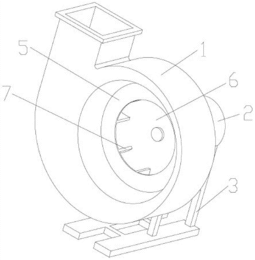
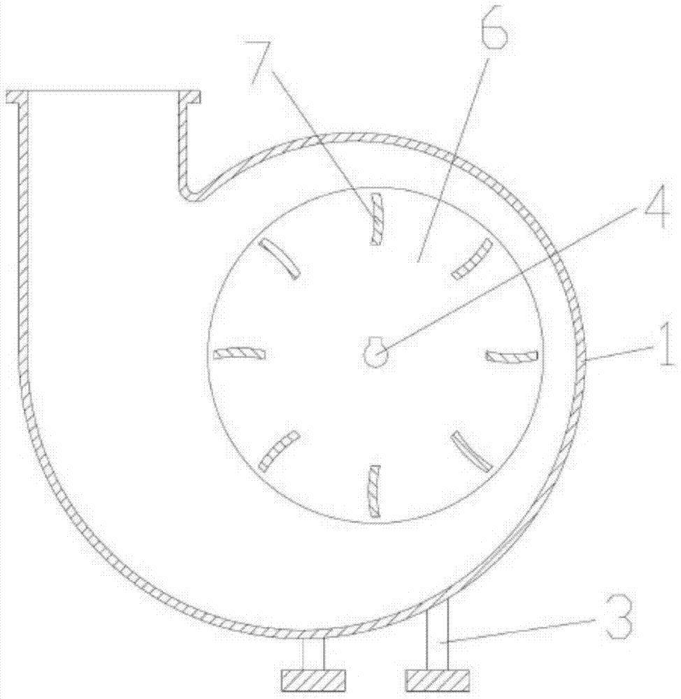
[0014] see Figure 1 to Figure 2 , a gas conveying device, comprising a casing 1, a motor 2 and blades, the rear end of the casing 1 is provided with a motor 2, a motor carrier 3 is provided below the motor 2, and the blades are arranged on the casing 1 Inside, it is connected with the transmission shaft 4 of the motor 2, and the blade includes a front cover 5, a rear cover 6 and a blade 7, and there are multiple blades 7 in an annular array between the front cover 5 and the rear cover 6. The blade 7 is vertically arranged between the front cover 5 and the rear cover 6; the blade 7 is welded with the front cover 5 and the rear cover 6; the blade 7 is arc-shaped; the outer center of the blade 7 The extension line that links to each other with the inner center passes through the center of circle of front cover 5 and back cover 6.

[0...


PUM


Abstract

The invention discloses gas transportation equipment. The gas transportation equipment comprises a case, a motor and a blade, wherein the motor is arranged at the back end of the case; the blade is arranged in the case and connected with a transmission shaft of the motor, the blade comprises a front cover, a back cover and a plurality of arc-shaped blade bodies, the plurality of blade bodies are annularly arrayed and vertically arranged between the front cover and the back cover; and an extension line connecting an inner side center with an inner side center of each blade body passes through centers of the front and back covers. According to the gas transportation equipment, the loss of transported gases is small, wear and breakage conditions of the blades are less, and the gas transportation equipment is durable in use and high in efficiency.

Description

technical field [0001] The invention relates to a mechanical device, in particular to a gas conveying device. Background technique [0002] Gas conveying equipment is a machine that relies on input mechanical energy to increase gas pressure and discharge gas. It is a driven fluid machine. Gas conveying equipment generally includes a casing, a motor, and blades. There is a motor at the rear end of the casing, and the blades are arranged in the casing and connected to the drive shaft of the motor. During operation, the drive shaft of the motor drives the blades to rotate, thereby achieving The purpose of exhaust gas. In the past, the blades of the blades were set between the front cover and the rear cover, and there would be a certain deviation between the blades relative to the center of the front and rear covers, which would cause the gas delivery equipment to discharge gas. In addition to the airflow direction that is required to be generated, there will also be airflow i...

Claims


Application Information

Patent Timeline
Patent Type & Authority Applications(China)
IPC IPC(8): F04D25/08F04D29/28F04D29/30
Inventor 陶钧
Owner ANHUI IND & TRADE VOCATIONAL TECHN COLLEGE
Learn More