Eureka AIR delivers breakthrough ideas for toughest innovation challenges, trusted by R&D personnel around the world.

Fan aerodynamic layout structure and method of a turbofan engine

A turbofan engine and aerodynamic layout technology, applied in the direction of engine components, machines/engines, liquid fuel engines, etc., can solve the problems of reduced fan reaction force, increased design difficulty, increased loss, etc., to achieve reduced diameter and weight, The effect of improving the flow capacity and increasing the bypass ratio

Active Publication Date: 2016-08-31
中科航星科技股份有限公司
View PDF4 Cites 0 Cited by
  • Summary
  • Abstract
  • Description
  • Claims
  • Application Information

AI Technical Summary

Problems solved by technology

However, the increase of the axial Mach number will further increase the relative Mach number of the blade tip inlet, forming a stronger shock wave in the blade channel, leading to the aggravation of the shock wave / boundary layer interaction, and in severe cases, large-scale Open separation, the loss increases sharply, which limits the efficiency of the compressor and the improvement of the stable working margin
Reducing the hub ratio of the fan inlet will reduce the reaction force of the fan, increase the load on the root of the fan stator blade, and increase the design difficulty; Imported wheel-to-hub ratio will make it difficult to arrange the blades on the small-sized wheel disc, which increases the difficulty of fan rotor processing

Method used


Image

  • Fan aerodynamic layout structure and method of a turbofan engine

Examples


Embodiment Construction

[0018] The present invention will be further described in detail below in conjunction with the examples, the following examples are explanations of the present invention and the present invention is not limited to the following examples.

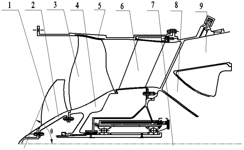
[0019] Such as figure 1 As shown, the present embodiment is used in the fan aerodynamic layout structure of a high-performance aviation turbofan engine, including fan rotor blades 3, fan rotor discs 4, fan stator blades 6 and fan outer casing 5, in order to improve the fan near the hub Flow rate and supercharging ratio, a non-full-blade high-pressure rotor composed of non-full-blade high-rotor blade 1 and non-full-blade high-rotor disc 2 is designed at the inlet of the fan rotor. The number of blades is the same, and the fan rotor rotates in the same direction as the fan rotating shaft 7 at the same speed. Further, the radial height of the non-full-blade high-pressure rotor blade is 15% to 30% of the height of the fan rotor blade, and the a...


PUM


Abstract

The invention discloses a fan aerodynamic layout structure and method of an inlet turbofan engine with a non-full-blade high-pressure rotor, which belongs to the technical field of aero-engine fans. The blades of the rotor are pressed to pressurize the airflow near the fan inlet disc. By rationally designing the non-full-blade high-pressure rotor at the fan inlet, the circulation capacity of the fan can be effectively improved, and the internal pressure ratio of the fan can be effectively improved at the same time. The invention can be directly applied to a high-performance turbofan engine, and can reduce the weight, fuel consumption rate and noise level of the turbofan engine without increasing the external dimension of the engine.

Description

technical field [0001] The present invention relates to a turbofan engine fan aerodynamic layout structure and method, in particular to a turbofan engine fan aerodynamic layout structure and method with a non-full blade high-pressure rotor at the inlet, which can maintain the fan efficiency and outer diameter basically unchanged It greatly improves the fan flow capacity and fan internal pressure ratio, especially suitable for high-performance aviation gas turbofan engines. Background technique [0002] The fan is one of the largest parts in size and weight in an aviation turbofan engine. Its performance not only directly determines the performance parameters such as the thrust-to-weight ratio and fuel consumption rate of the engine, but also affects the stability and reliability of the turbofan engine. Sex also plays a major role. On the premise that the size of the engine remains unchanged, increasing the upwind flow per unit area means that the work added by the fan incre...

Claims


Application Information

Patent Timeline
Patent Type & Authority Patents(China)
IPC IPC(8): F02K3/04F02C3/04F04D29/26
CPCF04D29/324F01D5/141F02K3/06F05D2220/36F05D2240/303
Inventor 卢新根赵胜丰朱俊强
Owner 中科航星科技股份有限公司
Why Eureka
Eureka Blog
Learn More