Integrated turbine set based on permanent magnetic and magnetic suspension technologies

A turbine unit and magnetic levitation technology, applied in the direction of electromechanical devices, mechanical equipment, electric components, etc., can solve the problems of low efficiency, limited life and high cost of turbomachinery, and achieve the effect of improving overall efficiency and avoiding friction loss

Active Publication Date: 2014-02-05
浙江博旭新能源科技有限公司
View PDF8 Cites 22 Cited by
  • Summary
  • Abstract
  • Description
  • Claims
  • Application Information

AI Technical Summary

Problems solved by technology

Due to different application industries and different working media, the above turbomachinery requires higher speed and tighter requirements. Many working media cannot be leaked due to flammable, explosive, highly toxic, and expensive.
[0003] Traditional turbomachinery uses various seals to solve the external leakage of the working medium, such as dry gas seals, mechanical seals, carbon ring seals, honeycomb seals, etc. The external supply system of the seals is very complicated, has a limited life, is expensive, and cannot Completely isolate the leakage of working medium
[0004] Most of the existing traditional turbines are driven by ordinary motors, and due to the limitation of their own working principles, the motors cannot directly reach the speed required by the turbine. Generally, it is necessary to solve the speed required by the turbine through gear transmission. The gear system is not only the system Complicated and will bring efficiency reduction and energy loss to the entire turbomachinery
[0005] Existing turbomachinery and generators use contact bearings (such as alloy sliding bearings, ball bearings, etc.), which generally require an external cooling and lubrication system, and the medium of this system may not be the same as the working medium of the turbine. Capacity, even chemical reactions, bearings also increase the power consumption of turbomachinery

Method used


Image

  • Integrated turbine set based on permanent magnetic and magnetic suspension technologies
  • Integrated turbine set based on permanent magnetic and magnetic suspension technologies

Examples


Embodiment Construction

[0024] The present invention will be described in detail below in combination with specific embodiments.

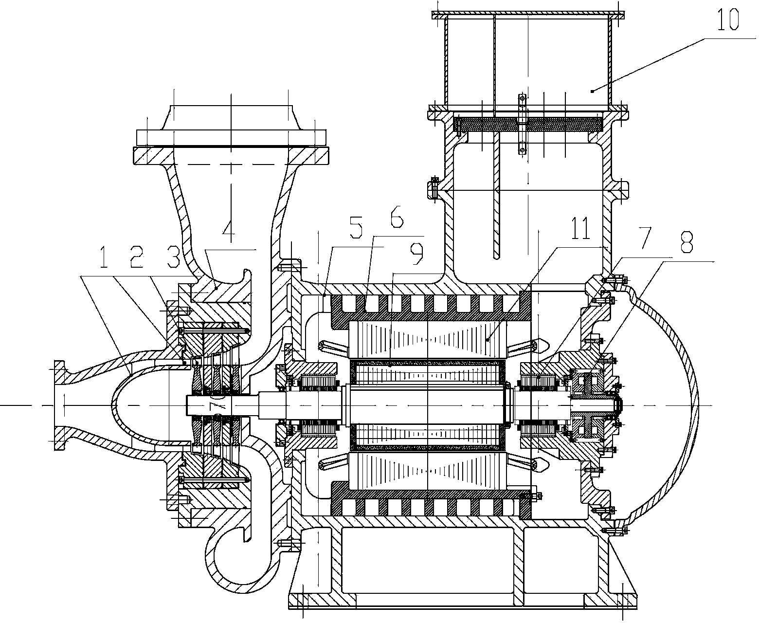
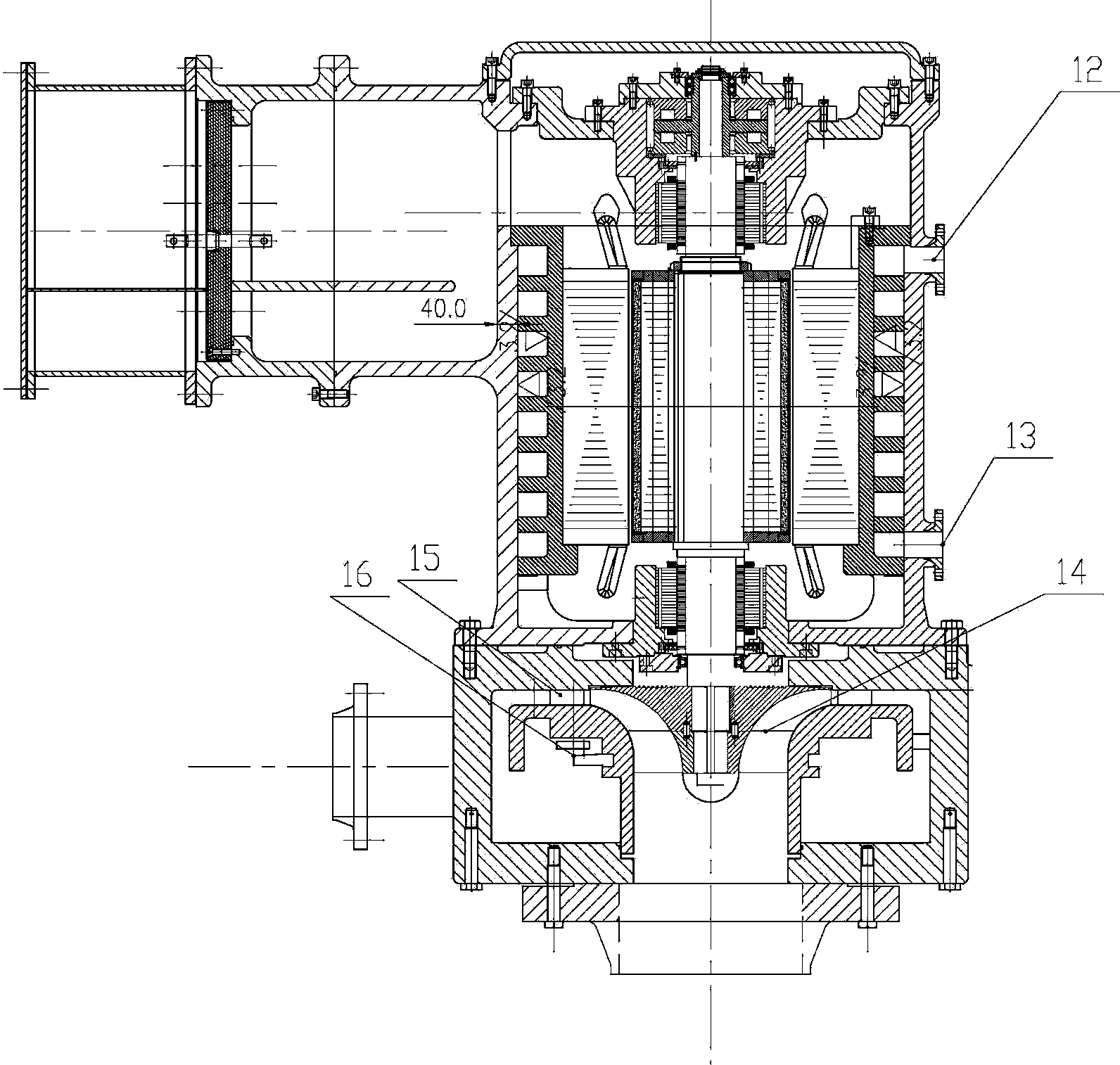
[0025] The integrated turbine unit based on permanent magnet and magnetic levitation technology involved in the present invention is designed with a turbine and a generator (or motor) on a rotating shaft with the same speed.

[0026] 1. When the turbine is an expander:

[0027] An integrated turbomachine consists of a turbine and a generator on the same shaft. One end of the rotating shaft is placed in the turbine, and the rotor blade 3 and the stator blade 2 are arranged outside the shaft, and the turbine volute 4 is arranged outside the rotor blade 3 and the stator blade 2; Set the exhaust port at the end. The other end of the rotating shaft is placed in the generator, the generator rotor 9 is arranged outside the shaft, and the generator stator iron core and winding 11 are arranged outside the generator rotor 9; the tail end of the shaft is arranged in turn with a ma...


PUM


Abstract

The invention relates to an integrated turbine set based on permanent magnetic and magnetic suspension technologies. Turbomachinery is high in sealing performance, complex in gear system and large in energy loss. A turbine and a generator (or a motor) of a full-sealing structure are arranged on the same rotary shaft. One end of the rotary shaft is arranged in the turbine to conduct gas expansion (or compression). The other end of the rotary shaft is arranged in the generator (or the motor), a generator rotor is arranged, and a generator stator core and a winding are arranged on the outside of the generator rotor. A magnetic suspension supporting bearing and a magnetic suspension thrust bearing are sequentially arranged at the tail end of the shaft. All components of the generator are arranged in a generator casing. The generator (or the motor) and the turbine keep the same rotation speed and adopt the same casing, shaft-end sealing is not required, and a work medium of the whole turbine set can be absolutely free of leakage. A magnetic suspension bearing achieves non-contact supporting of the rotor, friction loss of the bearing is avoided, and the overall efficiency of the turbine set is improved.

Description

technical field [0001] The invention relates to a turbine, in particular to an integrated turbine unit based on permanent magnet and magnetic levitation technology. Background technique [0002] With the continuous development of turbomachinery (Turbine machinery) technology, turbomachinery has been widely used in modern industry and aerospace fields, especially miniaturized turbines are more and more used, such as natural gas compressors (Natural gas compressor), oil well gas expander (gas expander), micro gas turbine (gas turbine), steam turbine based on ORC technology, etc. Due to different application industries and different working media, the above-mentioned turbomachinery has higher speed requirements and higher sealing requirements. Many working media cannot be leaked due to flammable, explosive, highly toxic, and expensive reasons. [0003] Traditional turbomachinery uses various seals to solve the external leakage of the working medium, such as dry gas seals, mec...

Claims


Application Information

Patent Timeline
Patent Type & Authority Applications(China)
IPC IPC(8): F01D15/10H02K7/14H02K7/18
Inventor 蒲亚民
Owner 浙江博旭新能源科技有限公司
Why Eureka
Try Eureka