
Sheathed-element glow plug

a glow plug and element technology, applied in the field of shielded element glow plugs, can solve the problems of impaired pressure measurement, damage to the diaphragm, and significant stress on the diaphragm, and achieve the effect of reliable measurement of the pressure prevailing in the chamber

Inactive Publication Date: 2010-05-11
ROBERT BOSCH GMBH +1
View PDF18 Cites 15 Cited by
  • Summary
  • Abstract
  • Description
  • Claims
  • Application Information

AI Technical Summary

Benefits of technology

[0004]The sheathed-element glow plug according to example embodiments of the present invention, having the features described herein, has the advantage that the pressure sensor is able to have a certain prestressing applied to it. Thereby, in particular, possible gaps between the individual elements in the force path between the heating pin and the pressure sensor are able to be prevented, so that a reliable measurement of the pressure prevailing in the chamber is made possible.
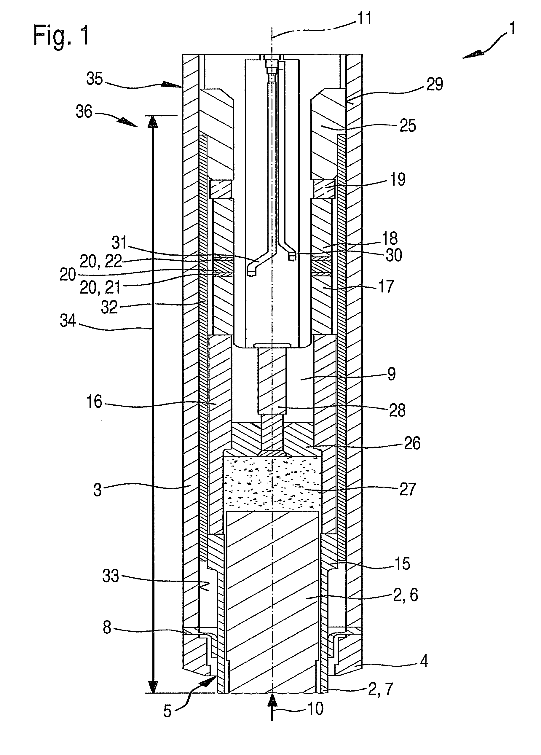
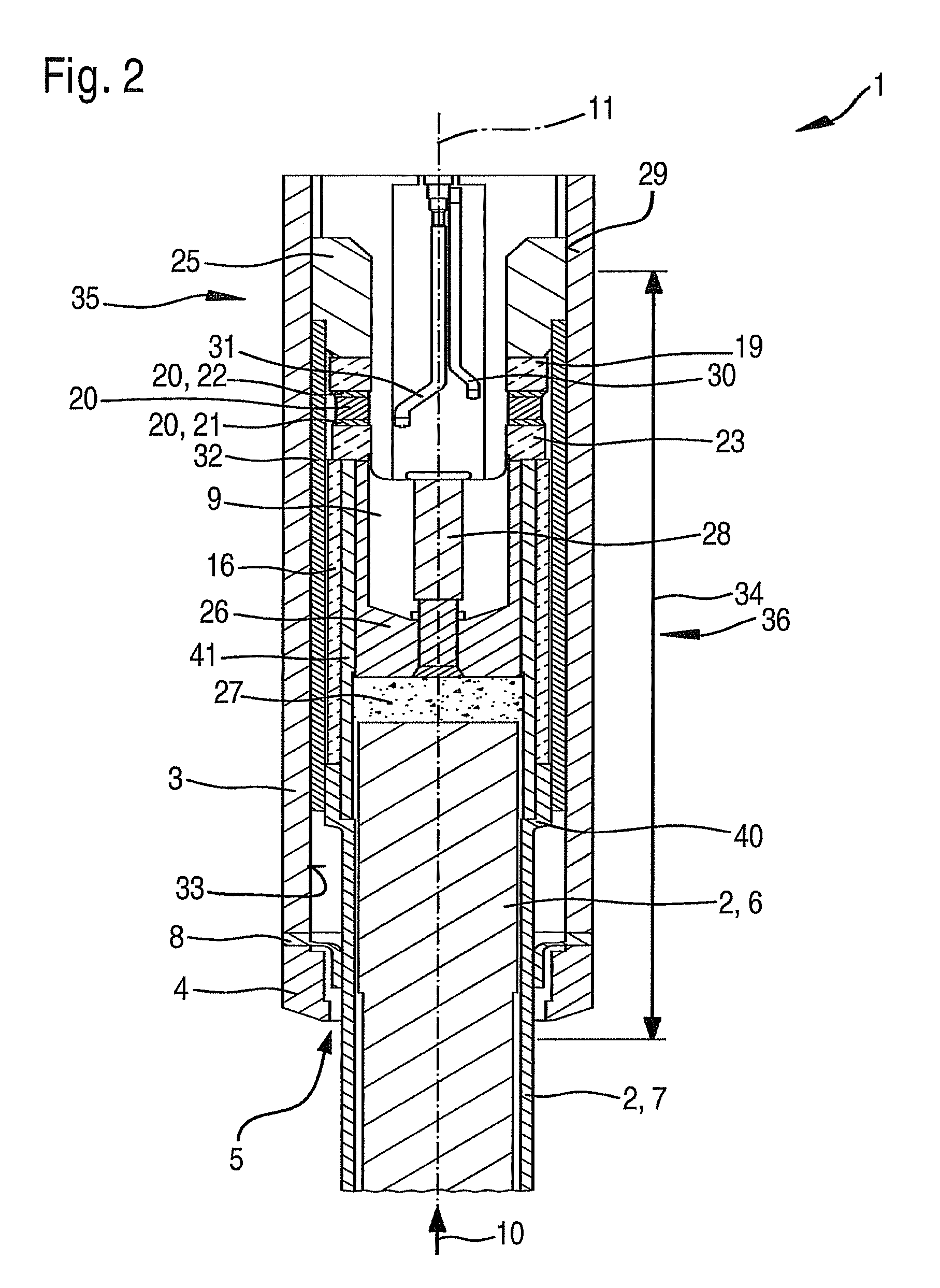
[0005]The prestressing element is advantageously designed as a sleeve-shaped prestressing element, the pressure sensor being situated in the interior of the sleeve-shaped prestressing element. Because of the sleeve-shaped prestressing element, the heat reaching into the housing, from the heating element and because of combustion gases, is able to be dissipated via the sleeve-shaped prestressing element to a fixing element and from it to the housing, as a result of which the temperature of the pressure sensor in operation is essentially constant, so that temperature-conditioned corruptions of the measuring results are reduced. Moreover, because of the positioning of the pressure sensor on the inside of the sleeve-shaped prestressing element, a compact construction of the sheathed-element glow plug is made possible, in which the pressure sensor is able to be situated closer to the heating element.
[0006]It is also advantageous that the prestressing element is situated at a distance from an inner wall of the housing. This avoids contact between the prestressing element and the housing, so that frictional losses are prevented. In addition, the influencing of the prestressing specified by the prestressing element is prevented in this manner.
[0008]It is advantageous that a metallic force transmission sleeve is provided, that the force transmission sleeve is in operative connection with the pressure sensor, that within the force transmission sleeve there is situated a metal terminal stud, connected to the force transmission sleeve, which is connected to a glow current line, and which is used for supplying electrical energy to the heating element, and that the force transmission sleeve is electrically insulated from the metal terminal stud. This makes possible a compact construction of the sheathed-element glow plug, in which the pressure sensor is able to be positioned close to the heating element, so that the frequency of natural vibrations may be shifted to higher frequency ranges. What is also made possible is the use of easily workable, and thus cost-effective, elements. In particular, instead of a ceramic force transmission sleeve, which is costly to process, a force transmission sleeve made of a metal may be used. The per piece costs of the sheathed-element glow plug may thereby be reduced.
[0010]Furthermore, it is advantageous that, for sealing the inner chamber from the chamber of the internal combustion engine, a metal diaphragm is provided which, on the one hand, is connected to the heating element and, on the other hand, to the housing, in the installed state of the sheathed-element glow plug, the metal diaphragm being partially mechanically unloaded by the amount of the prestressing force, with respect to the sum of the installation force and the prestressing force. The reduction in the stressing of the metal diaphragm conditional upon the prestressing force makes possible a flexible, particularly an elastic design of the metal diaphragm, in order to ensure that the measuring of the pressure has sufficient accuracy, damage to the metal diaphragm being prevented at the same time.

Problems solved by technology

The pressure-measuring glow plug described in German Published Patent Application No. 103 43 521 has the disadvantage that the diaphragm is exposed to considerable stresses when the pressure-measuring glow plug is incorporated in the cylinder, because of the required installation force, whereby damage to the diaphragm may occur.
Besides, the diaphragm is situated in the force path between the heating pin and the pressure sensor, so that the pressure measurement is impaired.
A further disadvantage of the pressure-measuring glow plug is the great distance of the pressure measuring sensor from the conical seal of the plug element, since, because of that, natural vibrations of the pressure-measuring glow plug are favored at low frequencies.
These natural frequencies may make the measurement of the pressure worse or impossible, and in an extreme case may result in the destruction of the pressure-measuring glow plug.
The components of the force path of the sheathed-element glow plug may have greatly different coefficients of thermal expansion, so that temperature changes lead to substantial differences in the expansion of the components.
In particular, instead of a ceramic force transmission sleeve, which is costly to process, a force transmission sleeve made of a metal may be used.

Method used


Image

  • Sheathed-element glow plug
  • Sheathed-element glow plug
  • Sheathed-element glow plug

Examples


Embodiment Construction

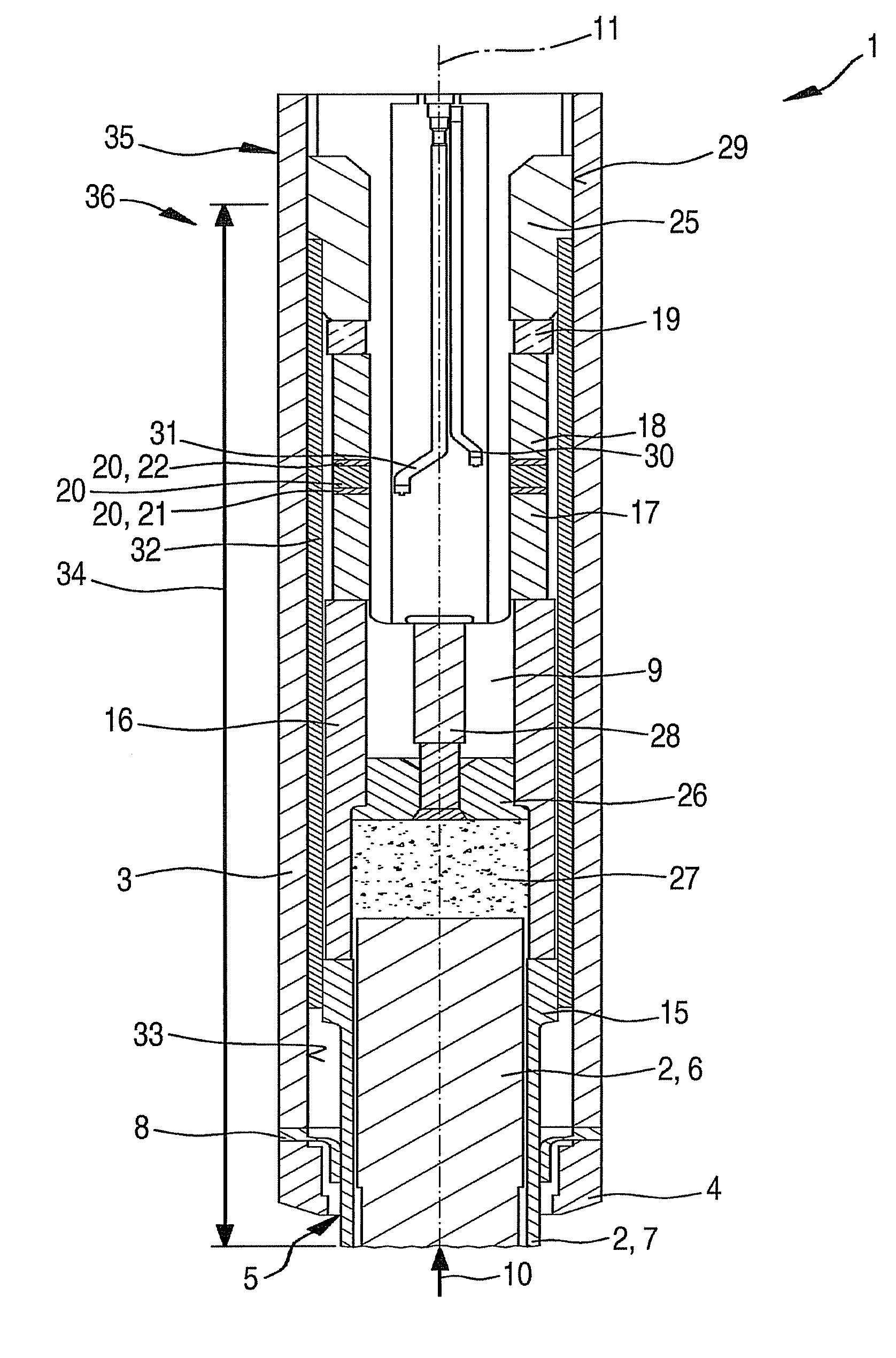
[0014]FIG. 1 shows a first exemplary embodiment of a sheathed-element glow plug 1 in an axial sectional representation. Sheathed-element glow plug 1 may be developed particularly as sheathed-element glow plug 1 for an air-compressing, self-igniting internal combustion engine. In the case of prechamber engines and swirl chamber engines, a pin-shaped heating element 2 of sheathed-element glow plug 1 extends into the chamber of the internal combustion engine and, in the case of engines having direct injections, into a chamber of the engine. However, sheathed-element glow plug 1 is also suitable for other applications.

[0015]Sheathed-element glow plug 1 has a housing 3. The housing includes a sealing cone 4, pin-shaped heating element 2 extending out of housing 3 into the chamber of the internal combustion engine, at an opening 5 of sealing cone 4 on the chamber side. Pin-shaped heating element 2 includes a ceramic heating member 6 and a support member 7 which circumferentially encloses ...


PUM


Abstract

A sheathed-element glow plug is used to be situated in a chamber in an internal combustion engine. The sheathed-element glow plug has a housing, a pin-shaped heating element, which extends partially from the housing and a pressure sensor which is situated in an inner chamber of the housing. A prestressing sleeve is provided, in this context, which applies a prestressing to the pressure sensor.

Description

FIELD OF THE INVENTION[0001]The present invention relates to a sheathed-element glow plug to be situated in a chamber in an internal combustion engine. The present invention also relates to a sheathed-element glow plug to be situated in a prechamber, swirl chamber or combustion chamber of an air compressing, self-igniting internal combustion engine.BACKGROUND INFORMATION[0002]A pressure-measuring glow plug for a Diesel engine is described in German Published Patent Application No. 103 43 521. The pressure-measuring glow plug has a plug element and a heating pin situated in the plug element. Furthermore, between the heating pin and the plug element there is a pressure sensor, the pressure sensor being influenced by the pressure, in the combustion chamber of the cylinder, that is transmitted by the heating pin. A diaphragm is also provided which seals the pressure sensor from the combustion chamber.[0003]The pressure-measuring glow plug described in German Published Patent Application...

Claims


Application Information

Patent Timeline
Patent Type & Authority Patents(United States)
IPC IPC(8): F23Q7/22
CPCF23Q7/001G01L23/222G01L23/10F02P19/028F23Q2007/002
Inventor KERN, CHRISTOPHHESS, REINHOLDZACH, REIKOKLEINDL, MICHAELWOLFER, PETERSCHOTT, STEFFENCAVALLONI, CLAUDIOSALTIKOV, PAVLOMUELLER, MICHAELBERTOLA, ANDREA
Owner ROBERT BOSCH GMBH
Learn More