
Oxyhemoglobin saturation detecting device combined with hanging type earphone

A detection device and blood oxygen detection technology, which is applied in diagnostic recording/measurement, medical science, sensors, etc., can solve problems affecting the normal life of the subject, discomfort, and difficulty in testing for a long time, so as to be suitable for long-term The effect of wearing

Inactive Publication Date: 2014-02-05
王卫东
View PDF9 Cites 15 Cited by
  • Summary
  • Abstract
  • Description
  • Claims
  • Application Information

AI Technical Summary

Problems solved by technology

[0004] In order to firmly fix the detection device to the detection position, especially when the subject is in motion, the clip needs to firmly clamp the earlobe or auricle, and the clamping of the auricle or earlobe for a long time will cause damage to the subject. Causes a very uncomfortable feeling for the tester, making the test difficult to perform for extended periods of time
In addition, the detection device is clamped on the ear. Due to the clamping force of the clip, the subject is not tested in a natural state. If the clip is too tight, the subject’s body will have a stress response, which will lead to inaccurate test results. precise
In addition, the detection device is clamped on the ear, which will also affect the normal life of the subject, such as answering the phone
For hearing-impaired patients who use hearing aids, it is an additional burden to install a blood oxygen detection device on the ear due to the need to install hearing aids on the ear

Method used


Image

  • Oxyhemoglobin saturation detecting device combined with hanging type earphone
  • Oxyhemoglobin saturation detecting device combined with hanging type earphone
  • Oxyhemoglobin saturation detecting device combined with hanging type earphone

Examples


Embodiment Construction

[0027] Below, the present invention will be described in detail in conjunction with the accompanying drawings.

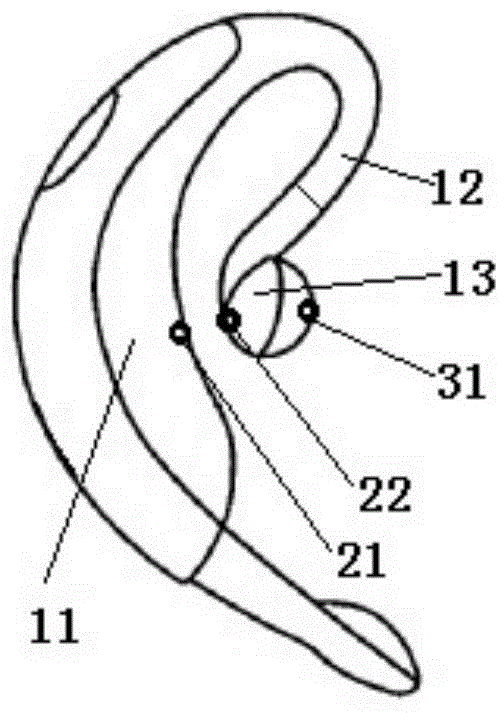
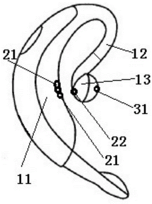
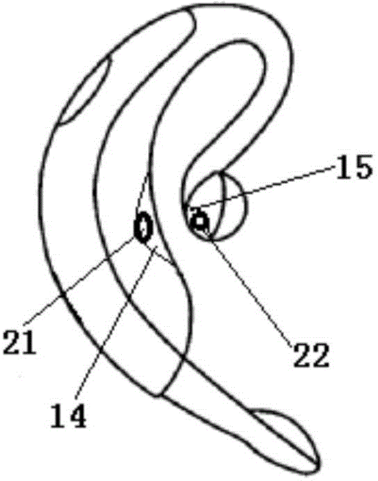
[0028] Such as figure 1 , 2 , 3, and 4, the blood oxygen saturation detection device combined with earphones of the present invention mainly includes an earphone part and a blood oxygen detection part.

[0029] The earphone part includes a "C"-shaped ear-hook part 11 and an earplug part 13, and the "C"-shaped ear-hook part 11 is connected with the earplug part 13 through a connecting part 12. Here, the connecting part 12 can be made of an elastic material for convenience. Activity of the earplug part 13.

[0030] Such as Figure 7 As shown, the blood oxygen detection unit mainly includes a first microcontroller and processor, an LED light source unit, and a photoelectric detection unit. Such as figure 1 , 2 As shown, the LED light source part 21 is disposed on the side of the "C"-shaped earhook part 11 corresponding to the back side of the auricle. The phot...


PUM


Abstract

The invention relates to an oxyhemoglobin saturation detecting device combined with a hanging type earphone, which comprises an earphone part and an oxyhemoglobin detecting part, wherein the earphone part comprises a C-shaped ear-hanging part and an earplug part; the oxyhemoglobin detecting part comprises an LED (Light Emitting Diode) light source part, a photoelectric detection part and a first micro-control processor; one of the LED light source part and the photoelectric detection part is arranged in the C-shaped ear-hanging part, so as to be corresponding to the rear side of an auricle of an ear of a detected person; the other one of the LED light source part and the photoelectric detection part is arranged in the earplug part, so as to be corresponding to the front side of the auricle of the ear of the detected person; a control and processing circuit is housed in the C-shaped ear-hanging part; a red light and a near-infrared light are emitted by the LED light source part; after the red light and the near-infrared light pass through the auricle, the red light and the near-infrared light are received by the photoelectric detection part; and a received detecting data is sent to the first micro-control processor by the photoelectric detection part and is sent to an external part after the received detecting data is processed.

Description

technical field [0001] The invention relates to a blood oxygen saturation detection device, in particular to an ear-hanging blood oxygen saturation detection device which can be comfortably worn on the ear. Background technique [0002] The pulse oximetry detector can continuously, non-invasively and real-time monitor the blood oxygen saturation and heart rate of the human body, providing an extremely convenient detection method for clinical diagnosis and personal health evaluation. At present, the measurement parts of the blood oxygen saturation detector mainly select tissues such as fingers and earlobes. [0003] CN202446094U discloses an ear clip-type blood oxygen detection device, which is clamped on the earlobe by a clip to perform blood oxygen detection. US8229532 also discloses an ear clip-type blood oxygen detection device, which is clamped on the auricle to perform blood oxygen detection, such as Figure 9 shown. [0004] In order to firmly fix the detection devic...

Claims


Application Information

Patent Timeline
IPC IPC(8): A61B5/1455
Inventor 王卫东彭福来李开元王国静
Owner 王卫东
Learn More