Rotor of a permanent magnet DC motor

A permanent magnet DC and rotor technology, used in DC commutators, electrical components, electromechanical devices, etc., can solve problems such as noise, difficulty in automatic winding of even-slot punching, and vibration, and achieve high power density and flexible winding. , the effect of reducing the number of

Active Publication Date: 2016-08-24
CHIAPHUA COMPONENTS SHENZHEN
View PDF6 Cites 2 Cited by
  • Summary
  • Abstract
  • Description
  • Claims
  • Application Information

AI Technical Summary

Problems solved by technology

[0003] The invention provides a short-distance winding permanent magnet DC motor rotor, which aims to solve the problems of current permanent magnet motors that the odd-numbered slots are easy to cause noise, vibration, etc., and the even-numbered slots will bring difficulties to automatic winding. The problem

Method used


Image

  • Rotor of a permanent magnet DC motor
  • Rotor of a permanent magnet DC motor
  • Rotor of a permanent magnet DC motor

Examples


Embodiment Construction

[0031] The following will clearly and completely describe the technical solutions in the embodiments of the present invention with reference to the accompanying drawings in the embodiments of the present invention. Obviously, the described embodiments are only some, not all, embodiments of the present invention. Based on the embodiments of the present invention, all other embodiments obtained by persons of ordinary skill in the art without creative efforts fall within the protection scope of the present invention.

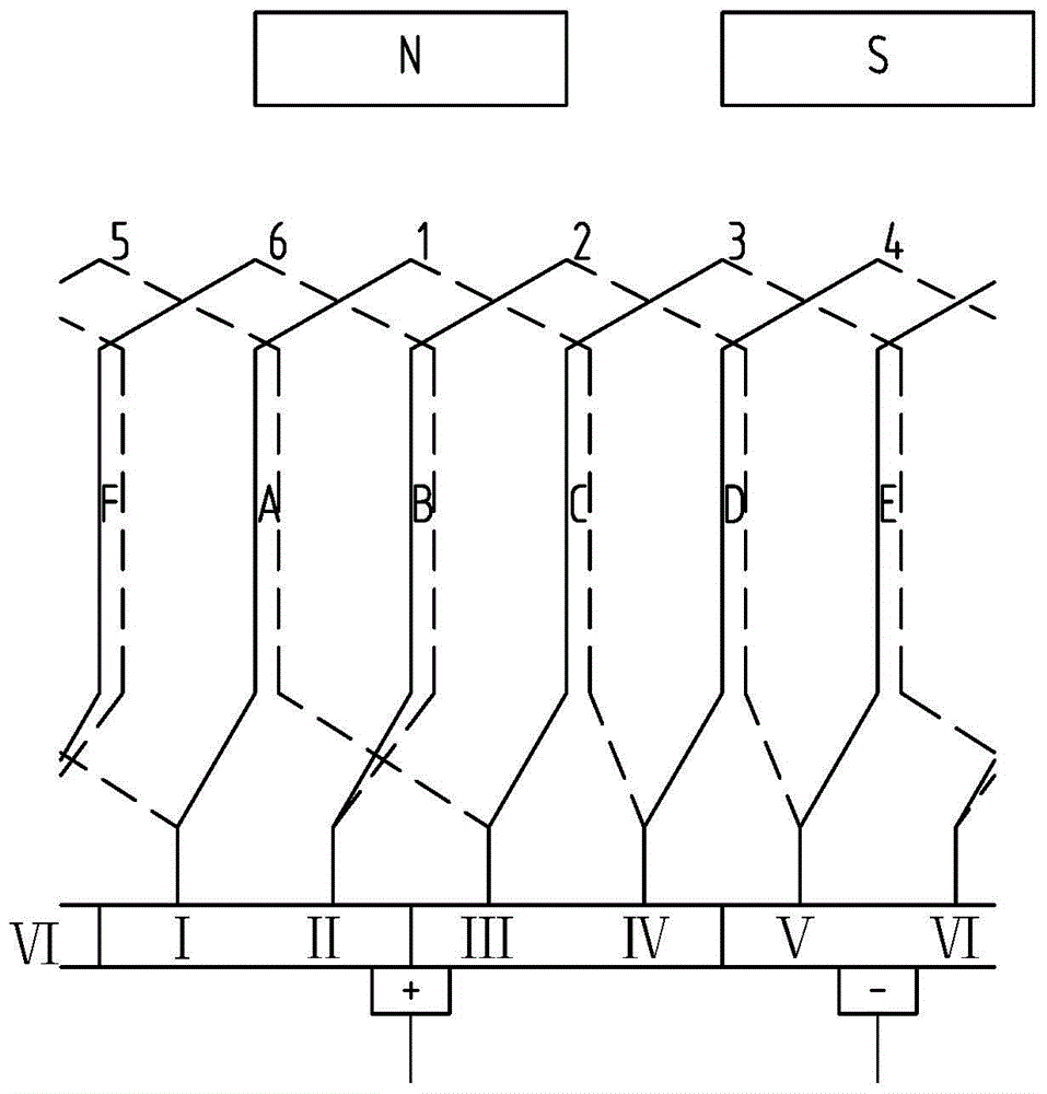
[0032] refer to figure 1 , figure 1 It is a rotor of a permanent magnet DC motor provided by an embodiment of the present invention. figure 1 Among them, 1, 2...6 represent coil 1, coil 2...coil 6, figure 1 Among them, A, B... represent slots, figure 1 Among them, Ⅰ, Ⅱ...Ⅵ represent hooks, among which, hooks Ⅰ and Ⅱ are on the same commutator piece, hooks Ⅲ and Ⅳ are on the same commutator piece, hooks Ⅴ and Ⅵ are on the same commutator piece, and the solid line...


PUM


Abstract

A rotor of a permanent magnet DC motor provided by the present invention, the rotor uses an even group of coils, and y1 is N is a natural number, so as to realize short wire winding; there are two hooks on each commutator piece, so as to reduce the number of commutator pieces, and also realize flexible winding and symmetrical winding. Moreover, the size of the end portion is also small, the processing time is short, the power density of the whole machine is high, the noise and vibration are small, and the manufacturing cost is low, and it can be applied to all even-numbered slot connections.

Description

technical field [0001] The invention relates to the field of motors, in particular to a rotor of a permanent magnet DC motor. Background technique [0002] Permanent magnet DC motor is a kind of DC motor that uses permanent magnets to establish a magnetic field. It has good mechanical characteristics and adjustment characteristics, and is widely used in the automobile industry. The permanent magnet DC motor is mainly composed of a stator, a rotor and a brush commutator. The rotor is composed of stacked armature punches. The punches can be divided into odd slot punches and even slot punches according to the number of slots. Odd slot punching can reduce the positioning torque generated by the armature teeth, but this structure has a large unilateral magnetic pull, which is likely to cause noise and vibration problems. It is necessary to consider optimizing the stator magnet or armature to weaken the magnetic pull, but The effect is limited. Even-numbered groove punching has ...

Claims


Application Information

Patent Timeline
Patent Type & Authority Patents(China)
IPC IPC(8): H02K3/16H02K3/28H02K13/04H02K23/02H02K23/26
Inventor 李政
Owner CHIAPHUA COMPONENTS SHENZHEN
Why Eureka
Try Eureka