A multi-stage pressure reducing valve

A pressure reducing valve and valve stem technology, which is applied in the field of multi-stage pressure reducing valves, can solve the problems of unbalanced lateral force, poor throttling stability, and damage to valve trims, so as to avoid cavitation and improve service life Long, well-structured effect

Active Publication Date: 2016-03-02
JIANGSU SHENTONG VALVE
View PDF5 Cites 0 Cited by
  • Summary
  • Abstract
  • Description
  • Claims
  • Application Information

AI Technical Summary

Problems solved by technology

The pressure reducing valve with one-stage throttling is not suitable for high pressure conditions, and the valve core structure of this type of pressure reducing valve matches the conical disc and the circular orifice, the lateral force is unbalanced, and the throttling stability is not stable. Well, cavitation is easy to occur under high pressure, which makes the valve trim prematurely damaged

Method used


Image

  • A multi-stage pressure reducing valve
  • A multi-stage pressure reducing valve

Examples


Embodiment Construction

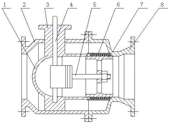
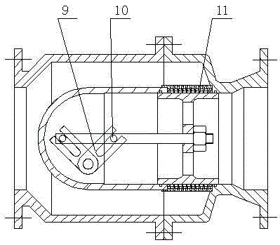
[0014] Such as figure 1 , 2 As shown, a multi-stage pressure reducing valve includes a left valve body 2, a right valve body 8, a valve stem 4, and a guide cylinder 1. The guide cylinder 1 is fixedly connected with the left valve body 2 through a shaft seat 3, and the valve stem 4 Radially through the guide tube 1 is fixed in the shaft seat 3, the valve stem 4 is located in the inner cavity of the guide tube 1 and connected to a shift fork 9, and the port of the guide tube 1 is fixedly connected to a multi-stage sleeve 6, the multi-stage sleeve 6 is provided with a plurality of taper holes 11, and a piston cylinder 7 is arranged in the inner cavity of the multi-stage sleeve 6 and the guide tube 1. The piston tube 7 is located on the same axis as the multi-stage sleeve 6 and the guide tube 1. A piston rod 5 is fixedly connected on the axis position, and a pin shaft 10 is fixedly connected to the front section of the piston rod 5, and the pin shaft 10 is connected with the shif...


PUM


Abstract

The invention provides a multi-stage reducing valve which comprises a left valve body, a right valve body, a valve rod and a guide tube. The guide tube is fixedly connected to the left valve body through a shaft base, the valve rod radially penetrates through the guide tube to be fixed in the shaft base, the section of the valve rod located in an inner cavity of the guide tube is connected with a shifting fork, a multi-stage sleeve is connected with a port of the guide tube, a piston cylinder is arranged in the inner cavity of the guide tube and the multi-stage sleeve, the piston cylinder, the multi-stage sleeve and the guide sleeve are located on the same axis, a piston rod is fixedly connected at the axis position of the piston cylinder, the front section of the piston rod is fixedly connected with a pin shaft, the pin shaft is connected with the shifting fork in a matching mode, and a plurality of reverse horn taper holes are formed in the multi-stage sleeve. The multi-stage reducing valve is good in stability and is not prone to generate flash and cavitation. A pressure reducing sleeve with different stages can be designed according to pressure difference of a process system. The aim of pressure reduction can be achieved.

Description

technical field [0001] The invention relates to a valve, in particular to a multi-stage decompression valve. Background technique [0002] The pressure reducing valve is to reduce the inlet pressure to a certain required outlet pressure by adjusting, so as to provide a certain pressure lower than the fluid pressure on the inlet side. At present, in the fluid delivery system, the decompression method usually adopts one-stage throttling, which uses the relative position between the conical disc and the circular orifice to change the throttling area, so that the flow velocity and fluid kinetic energy change, resulting in different Pressure loss, so as to achieve the purpose of decompression. The pressure reducing valve with one-stage throttling is not suitable for high pressure conditions, and the valve core structure of this type of pressure reducing valve matches the conical disc and the circular orifice, the lateral force is unbalanced, and the throttling stability is not s...

Claims


Application Information

Patent Timeline
Patent Type & Authority Patents(China)
IPC IPC(8): F16K47/08F16K17/00
CPCF16K3/265F16K47/08
Inventor 王建新张逸芳陆平
Owner JIANGSU SHENTONG VALVE
Why Eureka
Try Eureka