Pressure reducing valve and method thereof

A pressure reducing valve and disc technology, applied in the field of pressure reducing valves, can solve problems such as increased manufacturing costs, inability to respond to fluid pressure, complex design of pressure reducing valves, etc., to achieve stable guidance, increased life, and reduced axial rotational force Effect

Inactive Publication Date: 2007-10-03
PETRO OIL & LUBRICANT RES INST OF THE GENERAL LOGISITIC DEPT OF PLA
View PDF5 Cites 0 Cited by
  • Summary
  • Abstract
  • Description
  • Claims
  • Application Information

AI Technical Summary

Problems solved by technology

[0026] 1. In order to keep the piston 112 balanced in the vertical direction, it is necessary to correctly design the diameter of the inner chamber so that the pressure in the upper annular chamber 123 and the lower annular chamber 120 that pushes the piston 112 upwards is the same as that in the central chamber 118 that pushes the piston 112 downwards. The pressure inside is kept balanced, which undoubtedly complicates the design of the pressure reducing valve
[0027] 2. The formation of three inner chambers with different diameters requires precise machining of the cylinder and piston, resulting in increased manufacturing costs
[0028] 3. In the decompression valve, the power of the piston 112 movement comes from the difference between the fluid pressure in the cylinder above the piston 112 and the fluid pressure in the central chamber below the piston 112, so the piston 112 cannot correspond to the decompression valve The fluid pressure at the second fluid flow channel on the outlet side, so that the outlet pressure of the pressure reducing valve cannot be guaranteed to be stable

Method used


Image

  • Pressure reducing valve and method thereof
  • Pressure reducing valve and method thereof
  • Pressure reducing valve and method thereof

Examples


Embodiment Construction

[0105] The preferred embodiments of the present invention will be described in detail below in conjunction with the accompanying drawings.

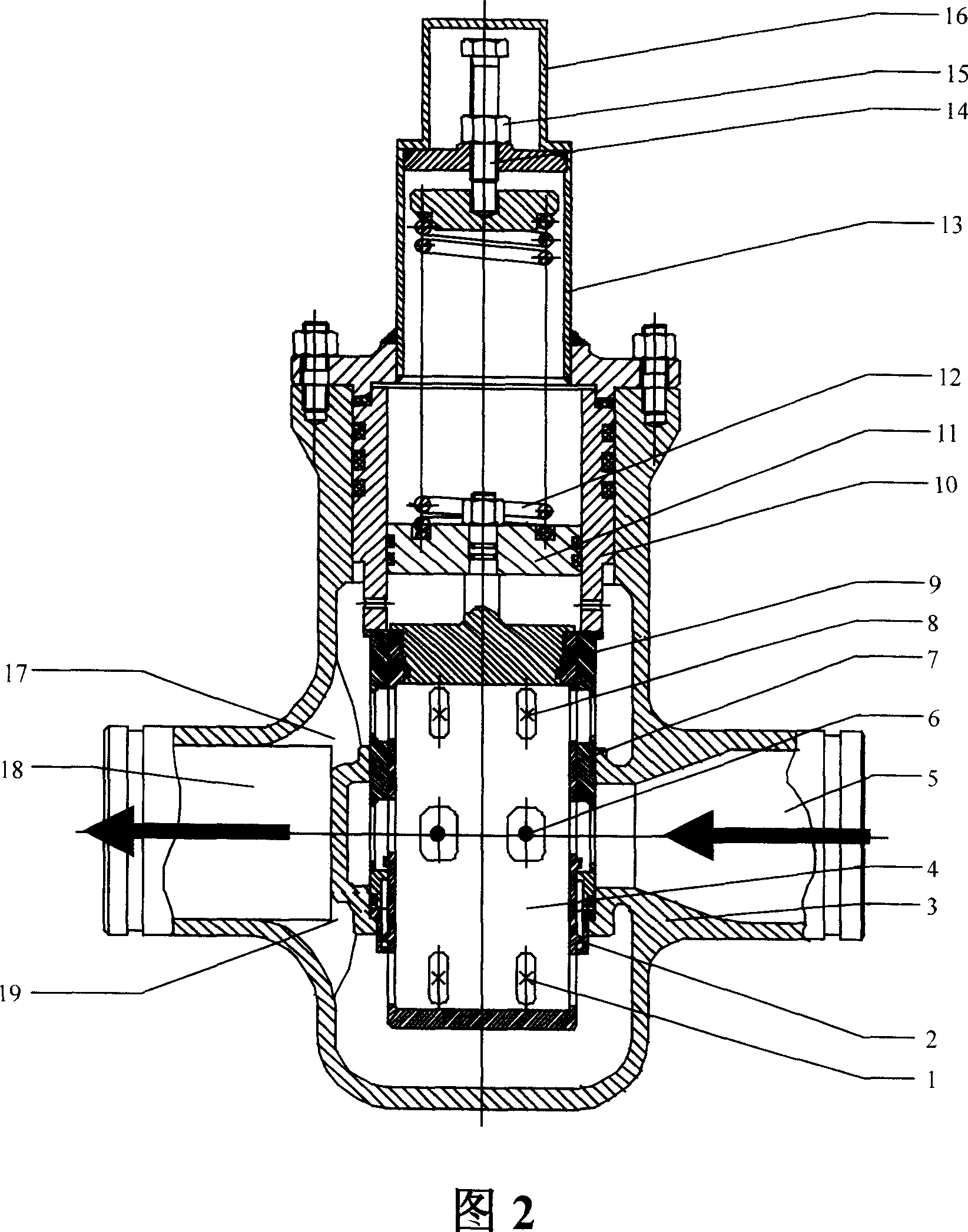
[0106] Fig. 2 is a schematic diagram showing the structure of a pressure reducing valve according to a specific embodiment of the present invention.

[0107] As shown in FIG. 2 , the pressure reducing valve according to the present invention mainly includes a valve body 3 , a valve core 4 and the like. The valve body 3 and the valve core 4 jointly define a fluid channel with two stages of throttling, and the channel connects the inlet 5 and the outlet 18 .

[0108] In practical applications, both ends of the valve body 3 of the pressure reducing valve are connected (eg, welded) to the fluid inlet and outlet joints of pipelines or equipment, wherein the inlet 5 of the valve body 3 is connected to a fluid pressure source (not shown). The machining dimensions above the mating surface of the valve seat 2 in the vertical direction of the inne...


PUM


Abstract

The present invention relates to a pressure reducing valve and its pressure reducing method. Said pressure-reducing valve includes the following components: valve body, valve core including valve flap and guide orifice sleeve and a pressure-regulating component. Said invention also provides the concrete structure of the above-mentioned every component, and provides the concrete steps of its pressure-regulating method.

Description

technical field [0001] The invention relates to a pressure reducing valve for a fluid delivery system, in particular to a pressure reducing valve and a pressure reducing method for a high pressure drop system. The invention also relates to a fluid delivery system comprising the pressure relief valve described above. Background technique [0002] The pressure reducing valve is to reduce the inlet pressure to a certain required outlet pressure by adjusting, so as to provide a certain pressure lower than the fluid pressure on the inlet side. The pressure reducing valve is installed on the pipeline leading to the fluid, regardless of the pressure of the fluid on the inlet side of the pressure reducing valve, it can maintain the fluid pressure on the outlet side at the required set pressure value. [0003] From the point of view of fluid mechanics, the pressure reducing valve is a throttling element whose local resistance can be changed, that is, by changing the throttling area,...

Claims


Application Information

Patent Timeline
Patent Type & Authority Patents(China)
IPC IPC(8): F16K17/04G05D16/10
Inventor 宋花平袁长友刘进立杨劲松郑勇何建设崔虹刘德东
Owner PETRO OIL & LUBRICANT RES INST OF THE GENERAL LOGISITIC DEPT OF PLA
Why Eureka
Try Eureka