A guide assembly method of oblique punching slider

An assembly method and slider technology, applied to metal processing equipment, perforating tools, manufacturing tools, etc., can solve the problems of low assembly efficiency, labor and time, and high work intensity, so as to improve efficiency, reduce costs, and reduce work intensity Effect

Active Publication Date: 2015-09-09
芜湖双林汽车部件有限公司
View PDF5 Cites 0 Cited by
  • Summary
  • Abstract
  • Description
  • Claims
  • Application Information

AI Technical Summary

Problems solved by technology

[0002] The oblique punching slider is a slider device used in stamping dies to punch punching holes on stamping products and to move obliquely with a punch inside. The punching holes include through holes or grooves of various shapes. The stamping die with multiple oblique punching sliders with different directions, different sizes and different inclinations on the complex curved surface requires that the assembly of each oblique punching slider must be strictly orthogonal to the surface on which it is located, otherwise it will cause punching problems in the product. In order to ensure that each oblique punching slider is strictly orthogonal to the surface where the shape and position are out of tolerance or flash burrs, the punch guide block must be fixed first and then the oblique punching slider, because when fixing the oblique punching slider, the oblique punching slider The slider and the punch guide block will have a deviation in relative spatial position due to the twitch clutch, so that when working, the oblique force applied by the oblique punch slider will cause a deviation in the direction of the force axis, and the punch of the oblique punch slider or the punch of the punch guide block will The guide hole of the head is damaged, which eventually leads to mold failure and scrapping of stamped products; for this reason, the existing technology adopts the method of using red lead to close the mold by the assembly fitter, and manually assembles each oblique punching slider one by one. Fixed, such an assembly operation is labor-intensive, time-consuming, high labor cost, low assembly efficiency and high work intensity. Therefore, the prior art has the problems and deficiencies of high work intensity, low efficiency, and high cost

Method used


Image

  • A guide assembly method of oblique punching slider
  • A guide assembly method of oblique punching slider

Examples


Embodiment Construction

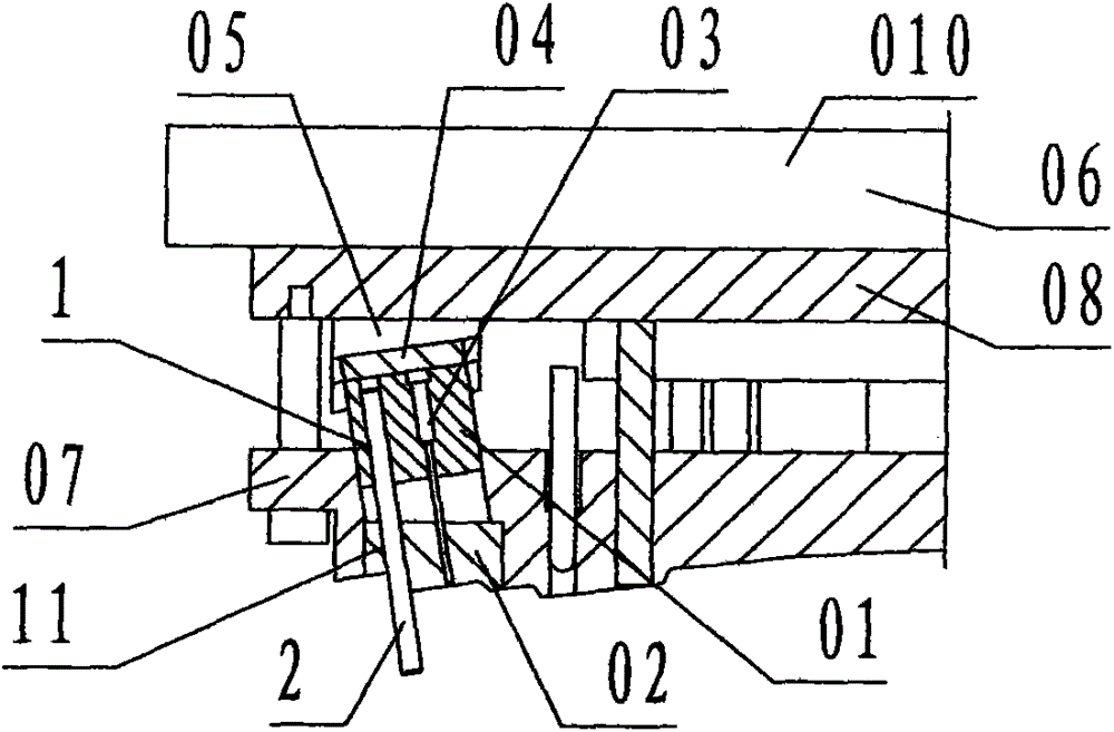
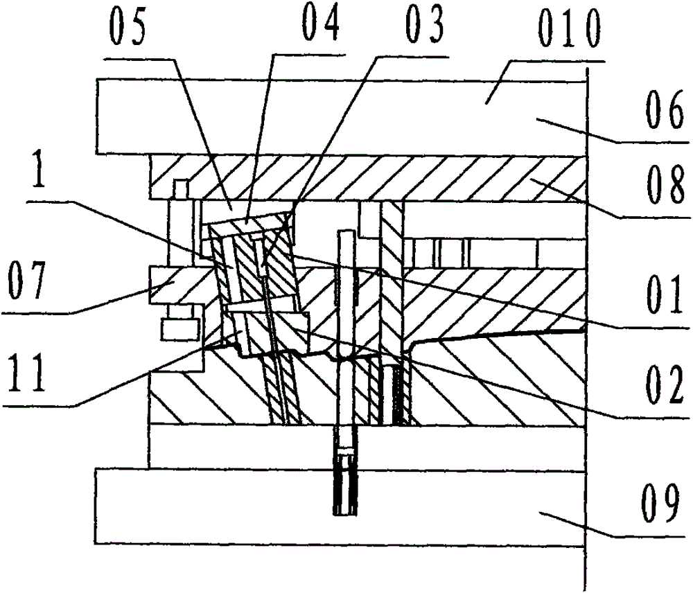
[0019] refer to figure 1 , figure 2 , a guide assembly method for an oblique punching slider of the present invention, including a guide process device and a guide assembly method, wherein: the guide process device includes A guide hole 1, B guide hole 11, guide pin 2, and the The A guide hole 1 is a circular through hole arranged in the punch fixing block 01; the B guide hole 11 is a circular through hole arranged in the punch guide block 02; the A guide hole 1, B The diameters of the guide holes 11 are the same, and the axes of the A guide hole 1 and the B guide hole 11 coincide on the same straight line and are parallel to the central axis of the punch placement hole in the punch fixing block 01;

[0020] The guide pin 2 is a cylindrical steel member, and the guide pin 2 is slidingly matched with the A guide hole 1 and the B guide hole 11;

[0021] The described guide assembly method is:

[0022] Step 1. From top to bottom, put the punch 03 into the punch placement hole...


PUM


Abstract

The invention discloses a guide process device and a guide assembling method of obliquely-punching sliding blocks. According to the guide process device and the guide assembling method of the obliquely-punching sliding blocks, a punch fixing block and a punch guide block are respectively provided with the same round through holes which are called A guide hole and B guide hole, and the axes of the A guide hole and the B guide hole coincide and are parallel with the central axis of a punch; meanwhile, a cylindrical steel guide pin is additionally provided, and the guide pin is arranged to be in sliding fit with the A guide hole and the B guide hole; according to the technical scheme, the guide pin, the A guide hole and the B guide hole form the guide process device, the guide pin and the punch are used for jointly limiting the spatial position relationship between the punch guide block and the punch fixing block in the guide assembling method, so that the problems and shortcomings of large working strength, low efficiency and high costs in the prior art can be overcome, and the assembly of a plurality of obliquely-punching sliding blocks of stamping dies of complex curved surfaces achieves the aims of reducing the working strength, improving efficiency and reducing costs.

Description

technical field [0001] The invention relates to a process device and an assembly method of a stamping die, in particular to a guiding assembly method for a plurality of oblique punching sliders in a complex curved surface stamping die. Background technique [0002] The oblique punching slider is a slider device used in stamping dies to punch punching holes on stamping products and to move obliquely with a punch inside. The punching holes include through holes or grooves of various shapes. The stamping die with multiple oblique punching sliders with different directions, different sizes and different inclinations on the complex curved surface requires that the assembly of each oblique punching slider must be strictly orthogonal to the surface on which it is located, otherwise it will cause punching problems in the product. In order to ensure that each oblique punching slider is strictly orthogonal to the surface where the shape and position are out of tolerance or flash burrs...

Claims


Application Information

Patent Timeline
IPC IPC(8): B21D28/34
Inventor 秦永新
Owner 芜湖双林汽车部件有限公司
Why Eureka
Try Eureka