Imaging device, imaging method
A camera device and the technology of the camera department, which can be used in image communication, TV, color TV parts, etc., and can solve the problem of image resolution reduction and other problems
- Summary
- Abstract
- Description
- Claims
- Application Information
AI Technical Summary
Problems solved by technology
Method used
Image
Examples
no. 2 Embodiment approach )
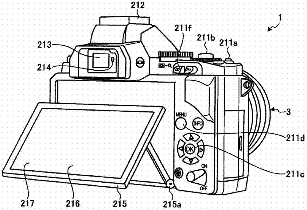
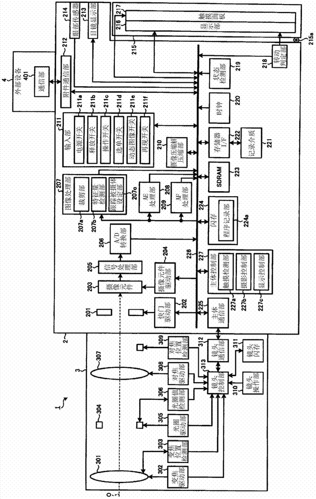
[0123] Next, a second embodiment of the present invention will be described. The imaging device of the second embodiment has the same configuration as the imaging device of the first embodiment described above. Therefore, the processing performed by the imaging device of the second embodiment will be described below. In addition, the same code|symbol is attached|subjected to the same structure as said 1st Embodiment, and it demonstrates.
[0124] Figure 10 It is a flowchart showing the outline of processing executed by the imaging device 1 of the second embodiment.
[0125] First, a case where the imaging device 1 is set to the shooting mode (step S201: Yes) will be described. In this case, the main body control unit 227 performs lens communication with the lens control unit 313 via the main body communication unit 225 and the lens communication unit 312 (step S202 ). At this time, the main body control unit 227 acquires lens characteristics from the lens unit 3 .
[012...
no. 3 Embodiment approach )
[0154] Next, a third embodiment of the present invention will be described. The imaging device of the third embodiment has the same configuration as the imaging device of the above-mentioned first embodiment. Therefore, the processing performed by the imaging device of the third embodiment will be described below. In addition, the same code|symbol is attached|subjected to the same structure as said 1st Embodiment, and it demonstrates.
[0155] Figure 16 It is a flowchart showing the outline of processing executed by the imaging device 1 of the third embodiment.
[0156] exist Figure 16 , step S301 to step S309 respectively correspond to the above Figure 10 step S201 to step S209.
[0157] In step S310 , the tracking subject setting unit 207 c starts tracking a target subject between adjacent images based on the feature value detected by the feature value detecting unit 207 b for the region including the touch position. Specific as Figure 17 As shown, the tracking su...
no. 4 Embodiment approach )
[0168] Next, a fourth embodiment of the present invention will be described. The imaging device of the fourth embodiment has the same configuration as the imaging device of the first embodiment described above, and only the processing executed by the imaging device is different. Therefore, only the processing executed by the imaging device of the fourth embodiment will be described below. In addition, the same reference numerals will be assigned to the same configurations as those of the above-mentioned first embodiment, and will be described.
[0169] Figure 19 It is a flowchart showing the outline of processing executed by the imaging device 1 of the fourth embodiment.
[0170] Steps S401 to S411 respectively correspond to Figure 10 step S201 to step S211.
[0171] In step S412 , the main body control unit 227 determines whether the coordinates of the slide position are within the optical zoom area of the lens unit 3 . When the main body control unit 227 determines ...
PUM
 Abstract
Description
Claims
Application Information
 - R&D
- Intellectual Property
- Life Sciences
- Materials
- Tech Scout
- Unparalleled Data Quality
- Higher Quality Content
- 60% Fewer Hallucinations
Browse by: Latest US Patents, China's latest patents, Technical Efficacy Thesaurus, Application Domain, Technology Topic, Popular Technical Reports.
© 2025 PatSnap. All rights reserved.Legal|Privacy policy|Modern Slavery Act Transparency Statement|Sitemap|About US| Contact US: help@patsnap.com


