
A real-time image fusion method based on visible light and near-infrared dual-band camera

A real-time image and fusion method technology, applied in image enhancement, image data processing, instruments, etc., can solve problems such as insufficient real-time processing, and achieve the effect of good real-time performance and simple hardware implementation

Active Publication Date: 2018-01-16
CHINESE AERONAUTICAL RADIO ELECTRONICS RES INST
View PDF4 Cites 0 Cited by
  • Summary
  • Abstract
  • Description
  • Claims
  • Application Information

AI Technical Summary

Problems solved by technology

[0005] In order to overcome the problem of insufficient real-time processing of complex image fusion algorithms, the present invention proposes a real-time image fusion method based on a visible light and near-infrared dual-band camera, which includes the following steps:

Method used


Image

  • A real-time image fusion method based on visible light and near-infrared dual-band camera
  • A real-time image fusion method based on visible light and near-infrared dual-band camera
  • A real-time image fusion method based on visible light and near-infrared dual-band camera

Examples


Embodiment Construction

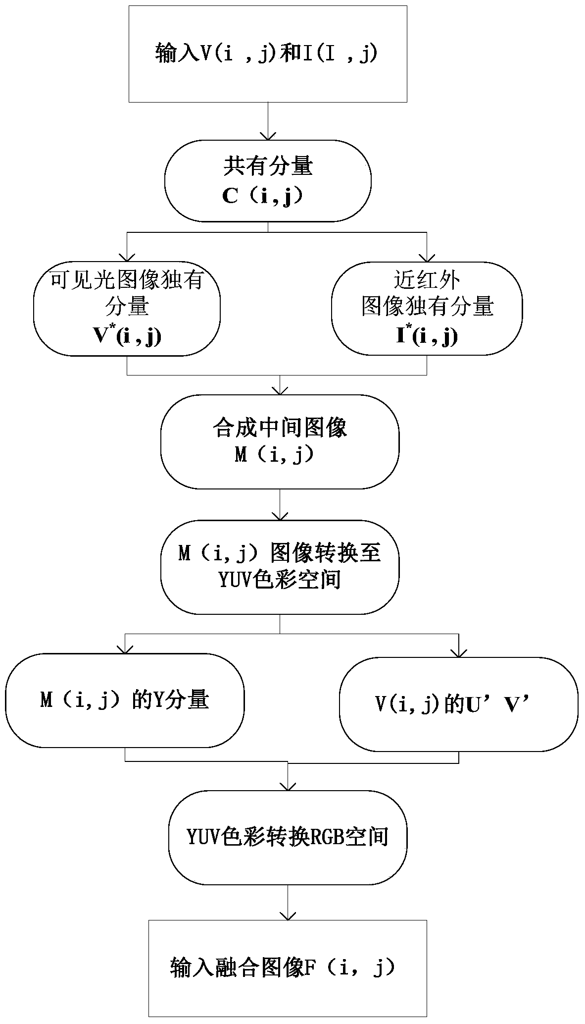
[0029] According to the real-time image fusion method based on visible light and near-infrared dual-band camera described in the manual, its processing flow is as follows figure 1 shown.

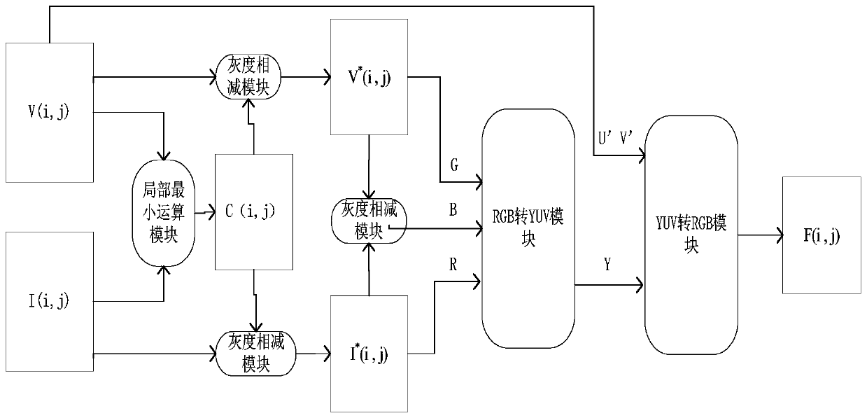
[0030] 1. Calculate the common components of the visible light image and the near-infrared image through the local minimum operator. Let the visible light image component be V(i,j) and the near-infrared image component be I(i,j). Then the common component C(i,j) of the two images can be expressed by formula (1)

[0031] C(i,j)=V(i,j)∩I(i,j)=min{V(i,j),I(i,j)} (1)

[0032] 2. The common component of visible light and near-infrared can be subtracted from the light image component to obtain the unique component V of the visible light image * (i, j), expressed as the following formula

[0033] V * (i,j)=V(i,j)–C(i,j) (2)

[0034] 3. Subtract the common component of visible light and near-infrared from the near-infrared image component to obtain the unique component I of the near-infrared im...


PUM


Abstract

A real-time image fusion method based on a visible-light and near-infrared dual-band camera of the present invention includes the following steps: 1. First, obtain the common component of the visible-light image and the near-infrared image through a local minimum operator; 2. Subtract the common component from the visible-light image Components to obtain the unique components of the visible light image; 3. Subtracting the common components from the near-infrared image to obtain the unique components of the near-infrared image; 4. Assigning the unique components of the near-infrared image and the unique components of the visible light image to the R and G component values ​​​​of the intermediate image , assign the difference between the unique component of the visible light image and the unique component of the near-infrared image to the B component of the intermediate image; 5. Convert the RGB component of the intermediate image into a YUV component, and then replace the U and V components of the visible light image with those of the intermediate image U and V components; Sixth, convert the replaced intermediate image into RGB components to obtain a fused image. The invention has a simple hardware structure and can simultaneously present the infrared target outline and visible light color information.

Description

technical field [0001] The invention relates to image fusion processing technology. Image fusion is the fusion of the visual information part of multi-sensor information fusion. It is to extract the information of each channel through certain image processing on the same target image collected by multi-source channels, and finally synthesize a unified image or comprehensive image characteristics for future use. Observation or further processing. In terms of military applications, image fusion is mainly used for positioning, identification, tracking, and reconnaissance of military targets, detection of concealed weapons, battlefield monitoring, and night flight guidance. Image fusion technology is also widely used in navigation, photography, medicine and other fields. Background technique [0002] The image fusion system has outstanding detection advantages, wide space-time coverage, high target resolution and measurement dimension, redundancy, complementarity, and relative...

Claims


Application Information

Patent Timeline
Patent Type & Authority Patents(China)
IPC IPC(8): G06T5/50
Inventor 周伟张飞飞杨爱良李立
Owner CHINESE AERONAUTICAL RADIO ELECTRONICS RES INST
Learn More