Electroluminescent device with high light emitting efficiency
An electroluminescent device and electroluminescent layer technology, which can be applied to electro-solid devices, electrical components, semiconductor devices, etc., can solve the problems of low luminous efficiency and cumbersome preparation process, and achieve a simple preparation process and easy large-scale mass production. , the effect of improving light extraction efficiency
- Summary
- Abstract
- Description
- Claims
- Application Information
AI Technical Summary
Problems solved by technology
Method used
Image

Examples
Embodiment 1
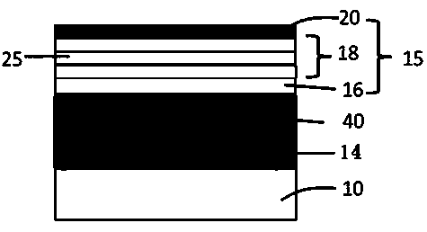
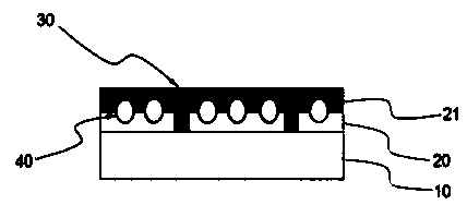
[0083] Such as Figure 4 As shown, the high-efficiency luminescent electroluminescent device of the present embodiment includes: a transparent substrate 1, a light scattering layer 2 on the transparent substrate 1, a surface smooth layer 3 on the light scattering layer 2, and a surface smooth layer 3 on the surface smooth layer 3. The electroluminescent layer; the light scattering layer 2 and the smooth surface layer 3 constitute the light extraction layer,
[0084] The light-scattering layer 2 includes egg-shaped light-scattering particles and a binder;
[0085] The surface smooth layer 3 includes inorganic nanoparticles and organic matrix with high refractive index;
[0086] The electroluminescent layer includes a transparent electrode layer 4 on the smooth surface layer,
[0087] An anti-short circuit layer 5 on the transparent electrode layer 4, an OLED light-emitting unit layer 6 with at least one light-emitting layer and a reflective electrode layer 7,
[0088] The su...
Embodiment 2
[0098] Example 2 Preparation of light scattering layer
[0099] 1) Preparation of egg-shaped light-scattering particles
[0100] Take 20g of titanium dioxide (DuPont R series), add 80g of solvent toluene and 1g of dispersant (Lubrizol Solsperse series), put 100g of grinding medium, put it in a ball mill, set the speed at 100rpm, and take a sample to analyze the kinetics after 5h Light scattering particle size. As shown in Figure 5, the effective particle size is 337.1nm.
[0101] 2) Preparation of light scattering layer
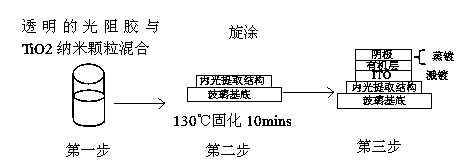
[0102] Take 10g of TiO prepared in the previous step 2Mix the suspension with 0.20 g of UV glue (Gulibao UV glue), take about 1mL of the mixture and add it dropwise on a 63.5*63.5mm glass substrate, and spin-coat at 1000 rpm to obtain a light-scattering layer. After UV curing for 15s, heat at 90 °C Baking for 15 minutes, the film thickness is 500-600nm.
Embodiment 3
[0103] Example 3 Preparation of light scattering layer
[0104] 1) Preparation of egg-shaped light-scattering particles
[0105] Mix 74.2g of dispersant (Lubrizol Solsperse series) and 2L of toluene in the grinding bucket evenly, add 742g of titanium dioxide (DuPont R series), stir for 10mins, start high-speed grinding, and take a sample to test the dynamic light scattering particle size after 1h. Such as Figure 6 As shown, the effective particle size is 284.2nm.
[0106] 2) Preparation of light scattering layer
[0107] Get 6.7g of the TiO prepared in the previous step 2 Suspension, after mixing 0.2g UV glue (Gulibao UV glue) and 3.1g toluene evenly, take 1ml of the mixture and add it dropwise on a 63.5*63.5mm glass substrate, spin coating at 1000 rpm to obtain a light scattering layer, and UV curing After 15 s, bake at 90°C for 15 min, and the film thickness is 400-500nm.
[0108] The surface morphology of the light scattering layer was analyzed. The surface roughnes...
PUM
 Abstract
Description
Claims
Application Information
 - R&D
- Intellectual Property
- Life Sciences
- Materials
- Tech Scout
- Unparalleled Data Quality
- Higher Quality Content
- 60% Fewer Hallucinations
Browse by: Latest US Patents, China's latest patents, Technical Efficacy Thesaurus, Application Domain, Technology Topic, Popular Technical Reports.
© 2025 PatSnap. All rights reserved.Legal|Privacy policy|Modern Slavery Act Transparency Statement|Sitemap|About US| Contact US: help@patsnap.com