Batteries with outgoing contacts of separate design

A technology of accumulators and contacts, applied in the field of power supply units, capable of solving problems such as low voltage or current amplitude, trouble, technical complexity, etc., to achieve the effect of eliminating the possibility of access

Active Publication Date: 2017-10-24
弗拉基米尔·切列姆内赫
View PDF5 Cites 0 Cited by
  • Summary
  • Abstract
  • Description
  • Claims
  • Application Information

AI Technical Summary

Problems solved by technology

[0003] Therefore, use of one or the other control device for AB conditional test controls, including those for dynamic parametric tests, by connecting an external resistive load, is understood to be the reaction of the AB given by the AB in response to a forcing function that functions with low voltage or current amplitudes in the form of periodic signals, such use faces serious technical complexities, inconveniences and disadvantages
[0004] Known ABs that allow continuous control of their parameters, for example, by means of measuring the dynamic parameters of the AB using known devices [US Patent No. 6002238, Int. Cl. H02J7 / 00, G01N27 / 416, 14.12.1999, Patent Application No. .09 / 152219, 11.09.1998], comprising a current sensor with voltage and current readout, a data processing unit, and a commutation element generating test measurement sampling data, requires many external connections and is limited by the fact that Effects: The control device itself is combined with the exchange element, located outside the AB and connected to the AB via Kelvin contact clips, which also represents a further disadvantage of the AB parameter control measurement scheme of the known device
[0005] Engineering solutions known in the prior art applicable to AB condition test control require at least one additional lead-out contact on the main body frame of the AB, which is essential for the formation of the link between the control unit and the data transmission bus is necessary, itself an undesired phenomenon and is undesirable because when the AB is used as an independent power supply source, for example for a vehicle, in this case from the point of view of the AB manufacturing technology Significant disadvantages are encountered both from the point of view of preventing unauthorized access

Method used


Image

  • Batteries with outgoing contacts of separate design

Examples


Embodiment Construction

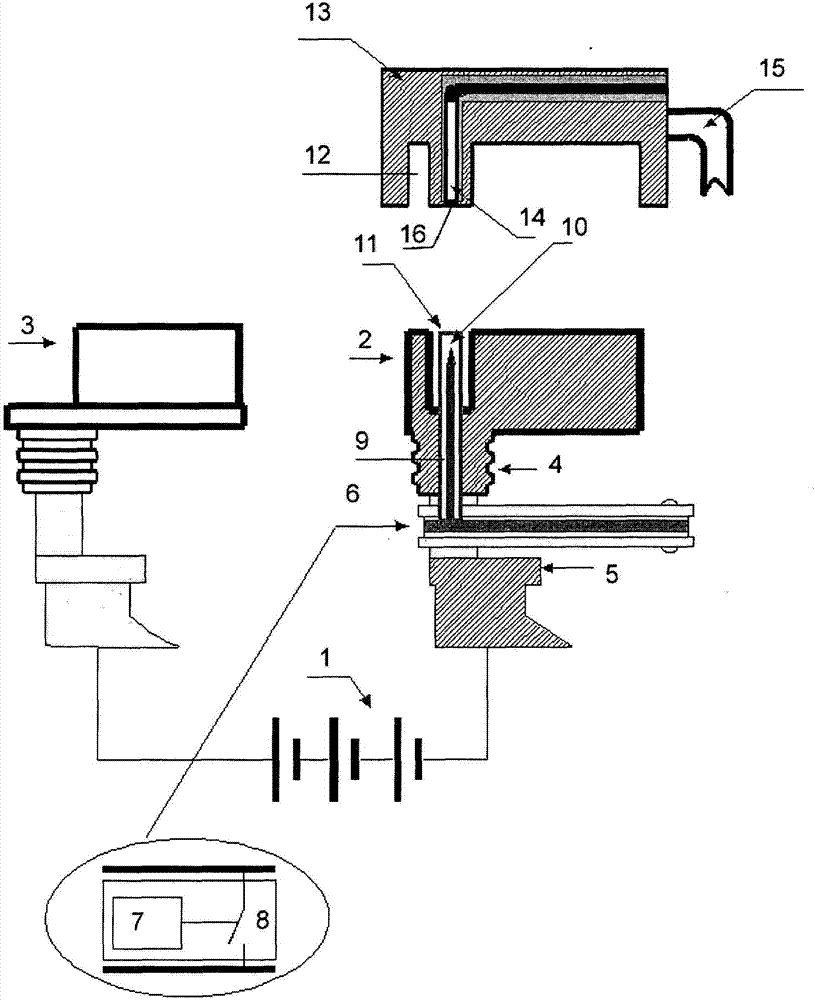
[0015] AB (1) includes outgoing contacts (2) and (3). The outgoing contact ( 2 ) has a split design which can be formed by several parts, a top part ( 4 ) and a lower part ( 5 ). The top part ( 4 ) and the bottom part ( 5 ) of the outgoing contact of separate design are arranged such that they can be combined with each other to form a single unit.

[0016] The configuration of the part ( 4 ) of the outgoing contact ( 2 ) and the configuration of the lower part ( 5 ) of separate design enables the unit ( 7 ) with connection to the electronic switching circuit ( 8 ), such as a control unit and / or The encapsulant (6) of the packaged chip of the AB condition test unit) is placed between these components.

[0017] In the top part (4) of the lead-out contact (2) of separate design there is a body cavity (9) which enables the placement of pin-type contacts integrated into said enclosure (6) of the packaged chip ( 10) (one or more). Said body cavity (9) is provided with an insulati...


PUM


Abstract

The invention relates to a storage battery with disconnected outlet contacts. The present invention relates to a power supply unit, by which it relates to an autonomous power supply device involving an accumulator (AB) mountable eg on a vehicle requiring multifunctional diagnostic and condition test control and protection against unauthorized access. The design of the AB according to the invention allows the integration of pin-type contacts (10) integrated into the enclosure (6) of a circuit (7) such as the AB control or diagnostic circuit, into separate designed lead-out contacts In the upper part (4) of (2), said above-mentioned part can be combined with another part (5) to form a single unit. The design provides coupling to external devices via I / O data links without the need for connecting cables, releasable connectors, or additional outgoing contacts on the AB housing. When referenced to vehicles, AB itself states that it is an ideal antitheft device that eliminates unauthorized access to control circuits.

Description

technical field [0001] The present invention relates to power supply units, in particular to autonomous power supply devices involving batteries (AB) mountable eg on vehicles requiring multifunctional diagnostic and condition test control and protection against unauthorized access. Background technique [0002] AB, known in the prior art [Н.И.κyрзуκOв, В.М.Ягнятинский, Акκyмy∏яторные бaTареи.КрaTкийсправочник, 2008, AKBplus, ISBN: 978-5-9698-0236-0] stands for electrical contacts The lead-out electrical contacts of the two poles (in particular, the positive and negative terminals) are made of metal or metal alloys, such as lead-calcium alloys or alloys with a small amount of antimony (the content of which ranges from 1.6 to 1.8%), and the lead-out Electrical contacts are used for the connection of the AB to external circuits including diagnostic means and control units as peripherals to such AB. [0003] Therefore, use of one or the other control device for AB conditional t...

Claims


Application Information

Patent Timeline
Patent Type & Authority Patents(China)
IPC IPC(8): H01M2/20H01M50/502H01M50/514
CPCH01M50/543Y02E60/10
Inventor 弗拉基米尔·切列姆内赫
Owner 弗拉基米尔·切列姆内赫
Why Eureka
Try Eureka