
Biotype artificial hip joint femoral component

A hip joint and femoral stem technology, applied in the field of biological artificial hip joint femoral stem, can solve the problems of prosthesis loosening, negative local bone tissue shaping, periprosthetic fractures, etc., so as to increase long-term stability and avoid prosthesis. The effect of loosening and reducing bone resorption

Active Publication Date: 2014-01-15
刘礼初 +1
View PDF5 Cites 2 Cited by
  • Summary
  • Abstract
  • Description
  • Claims
  • Application Information

AI Technical Summary

Problems solved by technology

[0005] The current biological (non-cemented) artificial hip femoral stem prosthesis has no structure to maintain its long-term stability after being inserted into the bone marrow cavity. The femoral stem of this structure bears weight by squeezing cancellous bone through the stem and trabecular bones transmit the body's gravity to the cortical bone, rather than directly to the cortical bone
Therefore, the abnormal stress and strain patterns generated by this gravity conduction mode may cause local bone resorption, resulting in osteoporosis and loosening of the prosthesis around the prosthesis; more seriously, it may even cause periprosthetic fractures
In addition, this inserted femoral stem prosthesis will also affect the interaction between local cells, which will have a negative effect on the shaping of local bone tissue.

Method used


Image

  • Biotype artificial hip joint femoral component
  • Biotype artificial hip joint femoral component
  • Biotype artificial hip joint femoral component

Examples


Embodiment 1

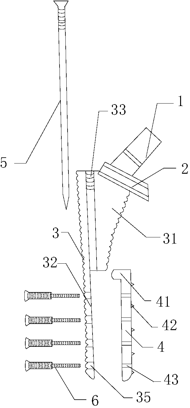
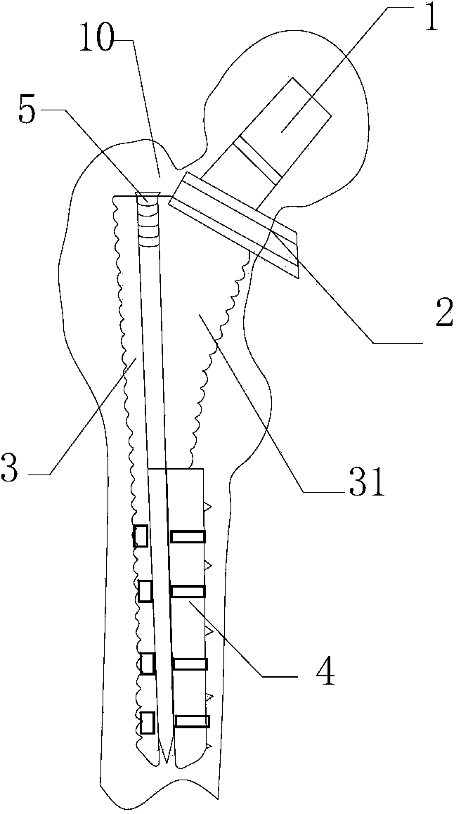
[0027] like figure 1 As shown, on the basis of the above scheme, the internal support device includes a main screw 5, and the fixed end 31 of the prosthesis handle 3 is provided with a threaded hole 33 matching the main screw 5, and the main screw 5 extends into the main screw 5 through the threaded hole 33. Between the endosteal separating steel plate 4 and the endosteal receiving steel plate 32 , the endosteal steel plate 4 is stretched toward the inner side of the femoral shaft 10 during the tightening process of the main screw 5 . The main screw 5 can not only expand the intima separation plate 4, but also fix the endosteal receiving plate 32 in the femur. This structure is mainly used for general replacement surgery, and the bone quality near the greater trochanter and the upper part of the femur is still relatively strong in patients without obvious osteoporosis ; At this time, the ordinary replacement structure of Example 1 is used during the operation, and no addition...

Embodiment 2

[0029] like Figure 4 As shown on the basis of the above-mentioned scheme, the internal support device includes at least two special-shaped screws 6; the special-shaped screw 6 includes a first diameter thread segment and a second diameter thread segment, and the diameter of the first diameter thread segment is larger than the second The diameter of the diameter thread section; the endosteal receiving steel plate 32 is provided with the first screw hole 35 matched with the first diameter thread section, and the described endosteal separation steel plate 4 is provided with the second diameter thread section matching The second screw hole 43 ; during the tightening process of the special-shaped screw 6 , the intima plate 4 is stretched toward the medial cortex of the femur 10 . On the basis of this embodiment, as a further improvement, the number of the special-shaped screws 6 is 4-8. Because the special-shaped screw 6 is made up of two thread segments with different diameters,...

Embodiment 3

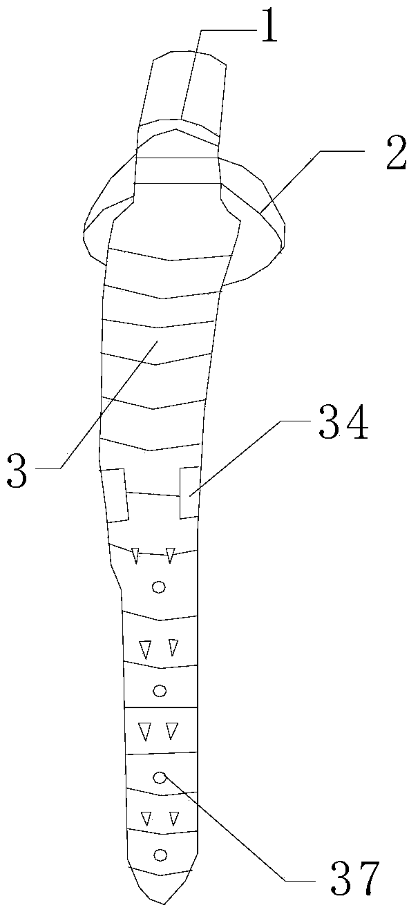
[0031] like Figure 5 As shown, on the basis of the above-mentioned embodiment 1 or 2, the prosthesis handle is lengthened as a whole, and several small screw holes 36 are provided on the surface of the fixed end 31 . The femoral stem with this structure is suitable for revision surgery. This structure is usually used for patients with osteoporosis around the greater trochanter, or even comminuted fractures. Short-stem prostheses cannot be used for repair. Small screw holes 36 on the proximal surface can be used to secure bone fragments 40 . The extra holes are conducive to the growth of new bone. The endosteal bearing plate and the endosteal separating plate can be fixed to the femoral shaft with stronger bone that is far away from the greater trochanter by using this long-handle prosthesis, which is suitable for osteoporosis around the greater trochanter and It is suitable for revision surgery of patients with periprosthetic fractures. Since there is no need to use bone c...


PUM


Abstract

The invention discloses a biotype artificial hip joint femoral component comprising a prosthesis femur neck, a neck and a component body comprising a fixed end and an isolated end; the isolated end comprises a periosteum carrier steel plate and a periosteum isolation steel plate; the periosteum carrier steel plate is arranged in one body with the fixed end; the biotype artificial hip joint femoral component also comprises an inner support device strutting the periosteum isolation steel plate towards the inner side of the femoral shaft and fixing the periosteum isolation steel plate on a medullary cavity cortical bone. The biotype artificial hip joint femoral component improves the structure of the femoral component, so the far end of the component body can be tightly pressed with the femoral shaft medullary cavity cortical bone, and the prosthesis can be stabilized and a gravity transmission mode can be improved so as to be close to natural stress and strain modes, thereby preventing femoral component prosthesis from loosening and surrounding bones from being broken; the biotype artificial hip joint femoral component can be made into a normal type and a prolonged type respectively used for normal replacement and revision.

Description

[0001] technical field [0002] The invention relates to the technical field of hip joint surface replacement, in particular to a biological artificial hip joint femoral stem. [0003] Background technique [0004] The hip joint is the largest weight-bearing joint in the human body. It is composed of the femoral head, acetabulum, joint capsule and surrounding soft tissue. Artificial hip replacement refers to the artificial joint prosthesis made of materials with good biocompatibility and mechanical properties through surgical methods to replace the femoral head and (or) acetabular articular surface destroyed by disease or injury. It is to remove the lesion, remove the pain, and restore the activity and original function of the joint. [0005] The current biological (non-cemented) artificial hip femoral stem prosthesis has no structure to maintain its long-term stability after being inserted into the bone marrow cavity. The femoral stem of this structure bears weight by squ...

Claims


Application Information

Patent Timeline
IPC IPC(8): A61F2/36
CPCA61F2/3662A61F2/3609A61F2/367A61F2/3676A61F2002/30331A61F2002/30507A61F2002/30556A61F2002/30579A61F2002/3069A61F2002/30841A61F2002/3631A61F2002/368A61F2002/3694
Inventor 刘效仿刘礼初
Owner 刘礼初
Learn More