
Micro-disturbance-torque environment simulation device suitable for spacecraft simulated test

An environmental simulation device and a technology of micro-interference torque, applied in the field of measurement, can solve the problem of no specific design method of the air-floating table, and achieve the effects of small temperature change, simple design principle, and small friction force/torque.

Active Publication Date: 2014-01-08
HARBIN INST OF TECH
View PDF5 Cites 32 Cited by
  • Summary
  • Abstract
  • Description
  • Claims
  • Application Information

AI Technical Summary

Problems solved by technology

[0005] In the paper "Application of air bearing platform in the simulation of satellite control system" (Aerospace Control, 2008, No. 5, pages 33-38), Li Jisu and others described the application of single-axis and three-axis air bearing simulation equipment in satellite control system. The application in the simulation, but the design method of the air bearing table is not specified

Method used


Image

  • Micro-disturbance-torque environment simulation device suitable for spacecraft simulated test
  • Micro-disturbance-torque environment simulation device suitable for spacecraft simulated test

Examples


Embodiment 1

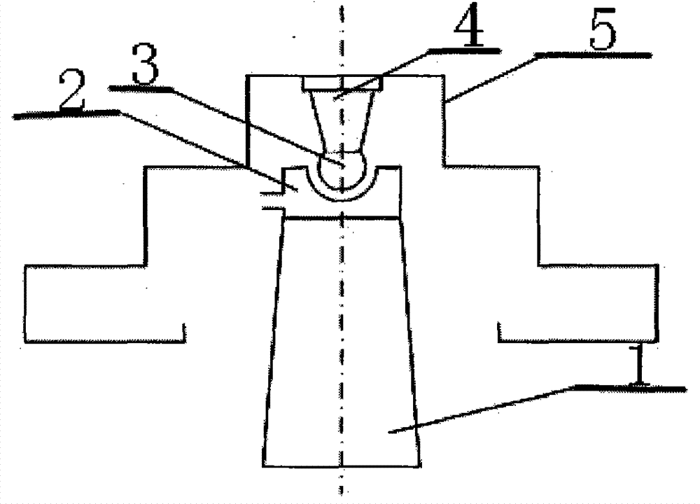
[0017] combine figure 1 , a micro-disturbance moment environment simulation device suitable for space vehicle simulation tests, comprising a base 1, an air-floating ball bearing pair, an adapter ring 4 and an instrument platform 5, and the air-floating ball bearing pair includes an air-floating ball shaft 3. Public buffer chamber 6, single row of annular space orifice 7, exhaust hole 8, annular space restrictor 9 and air-floating ball bearing 2, base 1 is installed on the foundation, and the lower end of air-floating ball bearing 2 is installed on the foundation On the seat 1, the air-floating ball shaft 3 can be suspended on the air-floating ball bearing 2, the air-floating ball shaft 3 can rotate freely in three dimensions, the upper end of the air-floating ball shaft 3 is provided with an adapter ring 4, and the adapter ring 4 is connected to the instrument platform 5 fixed connection, can be installed with different specifications of the instrument platform; the air float ...

Embodiment 2

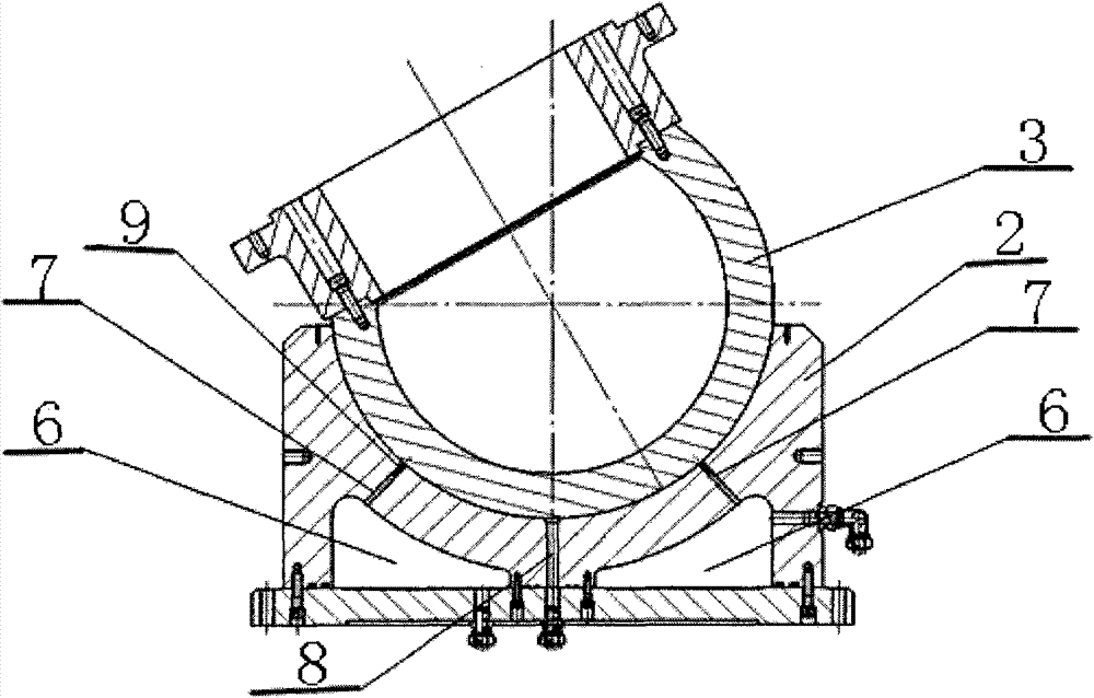
[0019] Such as figure 2 As shown, the air-floating ball bearing pair includes an air-floating ball shaft 3, a common buffer chamber 6, a single row of annular space orifices 7, an exhaust hole 8, an annular space restrictor 9 and an air-floating ball bearing 2, wherein The air-floating ball shaft 3 adopts a hollow design, which reduces its own weight and improves the effective load capacity while ensuring its own rigidity; the air-floating ball bearing 2 is designed with a single row of annular gap orifices 7, and the bottom of the air-floating ball bearing 2 is designed with one The air vent 8 improves the manufacturing process, avoids the turbulence problem of multi-row throttle holes and air vents, and improves the performance of the system; the air-floating ball bearing 2 is designed with a public buffer chamber 6. On the one hand, it can Play the role of filtering and stabilizing the air supply pressure, play a "damping" effect on the air bearing 2, and further improve t...

Embodiment 3

[0021] Such as figure 2 As shown, the annular gap restrictor 9 is embedded in the air bearing ball bearing, and an interference fit is selected to prevent air leakage on the mating surface or the restrictor falls off under pressure, hindering the normal operation of the air bearing pair . Since the restrictor is a separate part, it is not only convenient for processing and maintenance, but also ensures the same precision.


PUM


Abstract

The invention discloses a micro-disturbance-torque environment simulation device suitable for a spacecraft simulated test. The micro-disturbance-torque environment simulation device comprises a base, an air floating ball bearing pair, an adapter ring and an instrument platform. The air floating ball bearing pair comprises an air floating ball shaft, a public buffering cavity, single-row annular gap throttle holes, an air discharging hole, annular gap throttle devices and an air floating ball bearing, wherein the base is installed on a foundation, the lower end of the air floating ball bearing is installed on the base, the air floating ball shaft can be suspended on the air floating ball bearing, the air floating ball shaft can have a three-dimensional rotary freedom degree, the adapter ring is arranged at the upper end of the air floating ball shaft, and the adapter ring is fixedly connected with the instrument platform. The micro-disturbance-torque environment simulation device is simple in design principle, safe and reliable, and meanwhile has the advantages of an ordinary air bearing.

Description

technical field [0001] The invention relates to measurement technology, in particular to a micro-disturbance moment environment simulation device suitable for space vehicle simulation tests. Background technique [0002] Once the space vehicle is launched, it will be difficult to maintain, and its special operating environment makes the ground simulation test very important, so it must be fully tested and analyzed on the ground. Simulation of disturbance torque operating environment. [0003] China Invention Patent Application No. 200710064795.2, the patent name is "Single-axis full-physics simulation maglev platform", which discloses a single-axis full-physics simulation maglev platform, which is mainly used for full-physics simulation of the control system of spacecraft and other moving bodies , as a free turntable, the present invention overcomes the shortcoming of large friction torque of general semi-physical simulation mechanical turntables, but its magnetic levitatio...

Claims


Application Information

Patent Timeline
Patent Type & Authority Applications(China)
IPC IPC(8): B64G7/00
Inventor 王常虹夏红伟马广程宋效正李莉庞志成
Owner HARBIN INST OF TECH
Learn More