
Glue filling machine for high-speed continuous production line of honeycomb paper core

A technology of honeycomb paper core and production line, applied to cardboard articles, coatings, devices for coating liquid on the surface, etc., can solve the problems of unfavorable competition, increase the space occupied by equipment, and inconvenient disassembly of glue rollers, etc., and achieve improvement Glue effect, reduce horizontal floor space, and facilitate disassembly, cleaning and maintenance

Inactive Publication Date: 2014-01-08
SHANGHAI LVSHUN PACKAGING MACHINERY
View PDF10 Cites 4 Cited by
  • Summary
  • Abstract
  • Description
  • Claims
  • Application Information

AI Technical Summary

Problems solved by technology

[0002] Usually, the first choice for the production of honeycomb paper cores is to synchronously input the roll papers respectively set on the paper racks into a gluer equipped with at least two sets of rollers, and through the dislocation of the glue nozzles on each set of rubber rollers, the honeycomb of the paper after overlapping and gluing is realized. The main disadvantage of this processing method is the low production efficiency. In order to solve the above problems, Chinese patent 2006200908205 discloses a "honeycomb paper core four-paper horizontal gluing unit", which is characterized by: "in the horizontal There are four gluing rollers and four corresponding bearing rollers. "Its application is mainly composed of four gluing mechanisms with the same structure and arranged according to requirements, so that four papers can be glued together at one time per unit time. Indeed. The production efficiency has been improved, but the use of this equipment configuration will obviously greatly increase the manufacturing cost of the whole machine, which is not conducive to market competition
Moreover, the horizontally installed gluing roller increases the floor space of the equipment, and the position of the gluing roller is fixed and cannot be adjusted. The gluing roller is inconvenient to disassemble, which is not conducive to cleaning and maintenance.

Method used


Image

  • Glue filling machine for high-speed continuous production line of honeycomb paper core
  • Glue filling machine for high-speed continuous production line of honeycomb paper core
  • Glue filling machine for high-speed continuous production line of honeycomb paper core

Examples


Embodiment Construction

[0031] In order to make the technical means, creative features, goals and effects achieved by the present invention easy to understand, the present invention will be further described below in conjunction with specific illustrations.

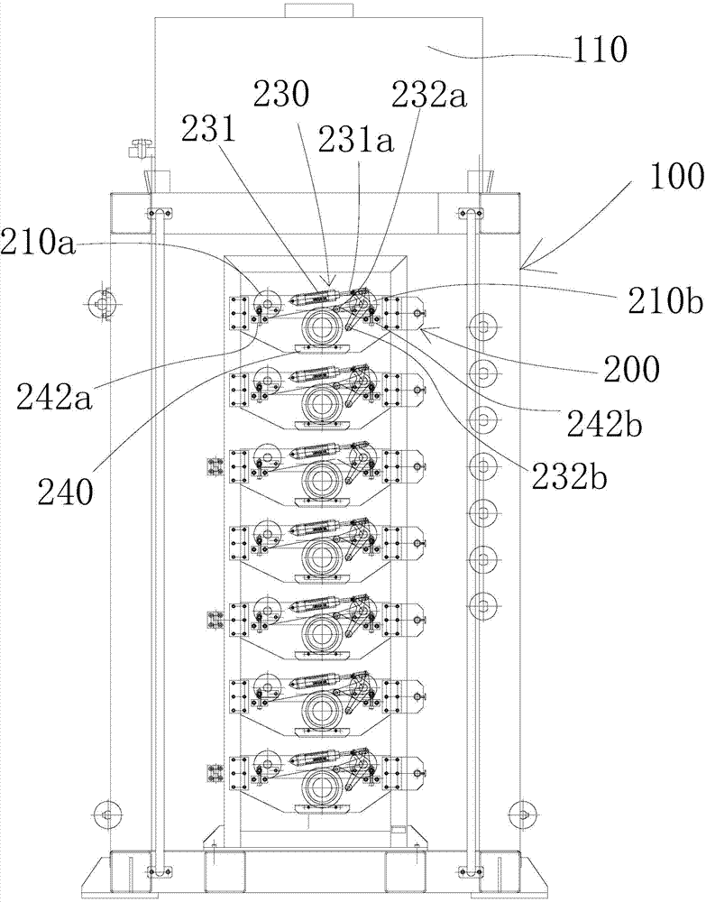
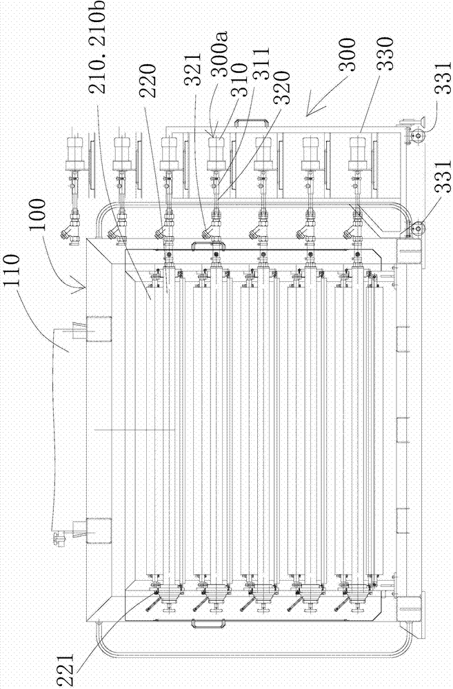
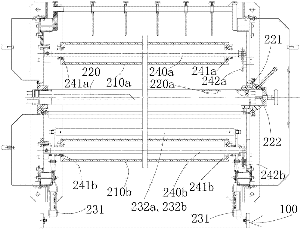
[0032] see Figure 1 to Figure 4 A gluing machine for a honeycomb paper core high-speed continuous production line shown includes a frame 100, a glue barrel 110, a number of gluing unit mechanisms 200, and a gluing mechanism 300 for injecting glue into the gluing unit mechanisms 200.

[0033] The glue bucket 110 is installed on the top of the frame 100. In the present embodiment, there are seven groups of gluing unit mechanisms 200, and the structure of each group of gluing unit mechanisms 200 is the same, and the seven groups of gluing unit mechanisms 200 are from top to bottom. The longitudinal structure is installed on the rack 100, which greatly reduces the horizontal footprint of the equipment.

[0034] Each gluing unit mechanism 200 all c...


PUM


Abstract

The invention discloses a glue filling machine for a high-speed continuous production line of a honeycomb paper core. The glue filling machine comprises a rack, a glue barrel arranged on the rack, a plurality of glue coating unit mechanisms which are arranged on the rack and are used for carrying glue coating on a paper plate, and a glue filling mechanism which is arranged on one side of the rack and is used for filling glue in the plurality of glue coating unit mechanisms, wherein the plurality of glue coating unit mechanisms are arranged on the rack from top to bottom in a vertical structure manner. The glue filling machine provided by the invention has the advantages that the plurality of glue coating unit mechanisms are arranged from top to bottom in the vertical structure manner, a horizontal floor space of equipment is greatly reduced, the glue coating effect is improved, and the disassembly, the cleaning and the maintenance are convenient.

Description

technical field [0001] The invention relates to a gluing machine for a honeycomb paper core high-speed continuous production line. Background technique [0002] Usually, the first choice for the production of honeycomb paper cores is to synchronously input the roll papers respectively set on the paper racks into a gluer equipped with at least two sets of rollers, and through the dislocation of the glue nozzles on each set of rubber rollers, the honeycomb of the paper after overlapping and gluing is realized. The main disadvantage of this processing method is the low production efficiency. In order to solve the above problems, Chinese patent 2006200908205 discloses a "honeycomb paper core four-paper horizontal gluing unit", which is characterized by: "in the horizontal There are four gluing rollers and four corresponding bearing rollers. "Its application is mainly composed of four gluing mechanisms with the same structure and arranged according to requirements, so that four p...

Claims


Application Information

Patent Timeline
IPC IPC(8): B05C1/10B05C11/00B05C11/10B05C13/02B31D3/02
Inventor 严伟明
Owner SHANGHAI LVSHUN PACKAGING MACHINERY
Learn More