
Multichannel configurable pulse generating method

A pulse generation, multi-channel technology, applied in the direction of electrical pulse generator circuits, etc., can solve the problems of large instantaneous current, circuit stability impact, squeezed logic resources, etc., to achieve strong flexibility, reduced resource occupancy, and easy The effect of transplantation

Active Publication Date: 2014-01-01
BEIJING INST OF CONTROL ENG
View PDF4 Cites 3 Cited by
  • Summary
  • Abstract
  • Description
  • Claims
  • Application Information

AI Technical Summary

Problems solved by technology

If the traditional pulse generation method is adopted, that is, an independent pulse generation module is used for each switch pulse instruction, only 80 pulses will be generated, and more than 45% of the internal resources of the FPGA will be consumed, which seriously squeezes the logic resources that can be used by other functions;
[0004] (2) The commands that the central controller needs to output include the on and off command pulses of various power supplies. When the same power supply on and off command pulses are generated at the same time, the internal circuit of the relay will be in an uncertain state, thus affecting the function of the components
If the traditional pulse generation method is used, since each pulse channel is independent, it is impossible to avoid the same power on / off command pulse being valid at the same time from the hardware point of view;
[0005] (3) When the pulses of many channels are valid at the same time, a large instantaneous current may be generated, which will affect the stability of the circuit
If the traditional pulse generation method is used, since each pulse channel is independent, it is impossible to avoid the situation that multiple command pulses are valid at the same time from the hardware point of view;
[0006] (4) The sequence and phase relationship of power switches of different channels in a single component need to be configurable, and the traditional pulse generation method does not consider the sequence and phase relationship between pulses

Method used


Image

  • Multichannel configurable pulse generating method

Examples


Embodiment Construction

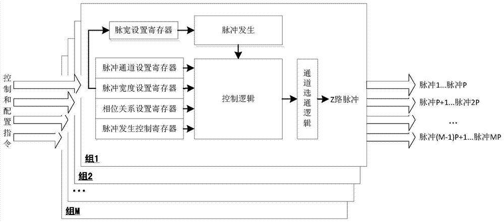
[0021] like figure 1 As shown, the multi-channel configurable pulse generation method of the present invention divides N pulses into M independent groups, and each group is mainly composed of three links: a pulse generation part, a pulse control logic part and a channel gating logic part. in:

[0022] (1) The pulse generation part is used to generate a pulse signal with a configurable pulse width. For example, an interface for configuring the pulse width of a pulse signal can be provided by setting the pulse width setting register;

[0023] (2) The pulse control logic part performs logic processing on the pulse signal generated by the pulse generation part. For example, the pulse channel setting register, pulse width setting register, phase relationship setting register and pulse generation control register can be used to provide and configure multiple pulse signal waveforms and their interrelationship interface;

[0024] (3) The channel gating logic part is used to select t...


PUM


Abstract

Provided is a multichannel configurable pulse generating method. The method comprises the steps of (1) dividing N pulse generating channels into mutual independent M sets, and enabling only one pulse output channel to be available for each set through a multichannel noise gate, wherein each set comprises P pulse generating channels,; (2) carrying out priority ranking on the P pulse generating channels contained in each of the M sets according to the control objects corresponding to the P pulse generating channels contained in the set; (3) setting the pulse widths and the pulse phases needed by the P pulse generating channels of each set respectively, wherein the pulse widths are detail numerical values, and the pulse phases are the phase difference values among the channels; (4) generating and outputting pulse signals with the width and phase needed by the channel with the highest priority firstly for each set, and then generating and outputting pulse signals with the width and phase needed by the channel with the second highest priority and so on until all the pulses of the P pulse generating channels of the set are output according to priority relationship in sequence.

Description

technical field [0001] The invention relates to a method for generating multiple pulses. Background technique [0002] The central controller is an important part of the robotic arm system of the space station experimental cabin, and it needs to be able to directly command the main backup motor power supply and line power supply of the 7 joints, 2 end effectors, and 2 hand-eye cameras in the experimental cabin robotic arm system Switch operation, a total of up to 80 pulse output channels. The command switch pulse output logic is realized by FPGA, and the following technical problems are encountered in the application: [0003] (1) The central controller needs to be able to generate a large number of component power switch pulse commands. It is estimated that the logic resources consumed by the single-channel pulse generation module account for 0.56% of the internal logic resources of the FPGA selected by the on-board computer. If the traditional pulse generation method is...

Claims


Application Information

Patent Timeline
Patent Type & Authority Applications(China)
IPC IPC(8): H03K3/02
Inventor 李圣龙周新发石冬生聂晓慧任宪朝李森肖爱斌
Owner BEIJING INST OF CONTROL ENG
Learn More