
Intelligent detection system for Duty parameters of machine tool

A technology of working condition parameters and intelligent detection, which is applied in the direction of manufacturing tools, metal processing equipment, measuring/indicating equipment, etc., can solve the problems of failure to realize real-time monitoring, insufficient intelligence of the detection process, and increased management difficulty, etc., to achieve high versatility Sex and practical value, promotion of machine tool processing automation, strong compatibility and applicability

Inactive Publication Date: 2014-01-01
SHANGHAI NORMAL UNIVERSITY
View PDF6 Cites 19 Cited by
  • Summary
  • Abstract
  • Description
  • Claims
  • Application Information

AI Technical Summary

Problems solved by technology

At the same time, CNC machine tools have high requirements on the control system and operators. Once the operation is wrong, it may cause heavy losses.
In some special processing occasions, human factors are always unavoidable in the detection and control of tool wear, oil pollution and machine tool parts damage, which not only hinders the process of mechanical manufacturing automation, reduces work efficiency, but also increases management difficulties
In the prior art, there are detection instruments applied to machine tools, but their functions are relatively single, and the parameters that can be detected are very limited; the wiring inside the machine tool is complicated; the detection process is not intelligent enough; it affects production; and real-time monitoring cannot be realized

Method used


Image

  • Intelligent detection system for Duty parameters of machine tool
  • Intelligent detection system for Duty parameters of machine tool
  • Intelligent detection system for Duty parameters of machine tool

Examples


Embodiment Construction

[0042] The present invention will be further described below in conjunction with specific examples.

[0043] Main hardware part:

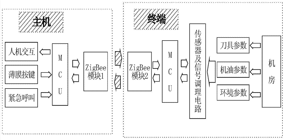
[0044] The detection system is designed as figure 1 As shown, the system includes two parts: the host and the terminal. The host is composed of MCU minimum system, ZigBee module 1, man-machine interface, membrane button circuit, and sound and light alarm circuit (emergency call). The terminal is composed of the minimum system of single-chip microcomputer, ZigBee module 2, tool parameter detection module, engine oil parameter detection module, and environmental parameter detection module. Among them, ZigBee module 1 and ZigBee module 2 adopt the same hardware circuit.

[0045] The system uses the stabilized power supply obtained by AC-DC conversion from the mains as the power supply for the system. The host sends corresponding control commands to the terminal through the ZigBee module 1 according to the requirements. After receiving the command,...


PUM


Abstract

The invention relates to an intelligent detection system for Duty parameters of a machine tool. The system is characterized by comprising a host part and a terminal part; the control center of the host part is a host MCU (Microprogrammed Control Unit); the control center of the terminal part is a terminal MCU, a tool parameter detection module is used for online detecting dynamic parameters of a tool in a machining process, a machine oil parameter detection module is used for online detecting machine oil parameters in a machine tool working process, an environmental-parameter detection module is used for online detecting environmental parameters, and wireless data transmission is realized by a first wireless data module and a second wireless data module; values of detected parameters and time-varying dynamic curves of the values are displayed in an LCD (liquid crystal display) liquid crystal circuit of a human-computer interaction interface; the host MCU is used for judging whether the machine tool is in a good working environment, whether machine oil is in a good working state and whether the tool is worn; when the values of the detected parameters exceed preset threshold values of software and hardware, an alarm circuit is used for automatic alarming.

Description

technical field [0001] The invention relates to an intelligent detection system for machine tool working condition parameters. Specifically, it performs online automatic judgment and alarm by detecting the environmental parameters of the machine room where the machine tool is located and the changes in the state parameters of the machine tool and cutting tool during the cutting process. system. Background technique [0002] With the rapid development of industrial technology, CNC machine tools with high automation and low labor intensity are more widely used in the processing and manufacturing industry. The maintenance and maintenance of machine tools has become a key issue in the field of processing and manufacturing. At the same time, CNC machine tools have high requirements on the control system and operators. Once the operation is wrong, it may cause heavy losses. In some special processing occasions, human factors are always inevitable in the detection and control of ...

Claims


Application Information

Patent Timeline
Patent Type & Authority Applications(China)
IPC IPC(8): B23Q17/09B23Q17/12B23Q17/00
CPCB23Q17/00B23Q17/007B23Q17/0952B23Q17/0957B23Q17/0971B23Q17/0985
Inventor 林军毛显源康琪叶能黄剑李绍香刘静
Owner SHANGHAI NORMAL UNIVERSITY
Learn More