
Gear edge and corner grinding machine

A technology for grinding machines and gears, which is applied in the direction of belts/chains/gears, gear teeth, mechanical equipment, etc., which can solve problems such as low efficiency, poor adaptability to gear chamfering, and poor processing accuracy, and achieve high efficiency and good processing accuracy , good adaptability

Inactive Publication Date: 2014-01-01
PINGYANG WUJING MACHINERY MFR FACTORY
View PDF7 Cites 0 Cited by
  • Summary
  • Abstract
  • Description
  • Claims
  • Application Information

AI Technical Summary

Problems solved by technology

[0003] The purpose of the present invention is to overcome the shortcomings of the current gear chamfer grinding equipment, such as poor machining accuracy, low efficiency, and poor adaptability to gear chamfers with different tooth inclinations, and provide a machine with good machining accuracy and high efficiency. Higher gear chamfering machine with better adaptability to gear chamfering with different tooth inclinations

Method used


Image

  • Gear edge and corner grinding machine
  • Gear edge and corner grinding machine

Examples


Embodiment Construction

[0019] The present invention will be further described below in conjunction with the accompanying drawings.

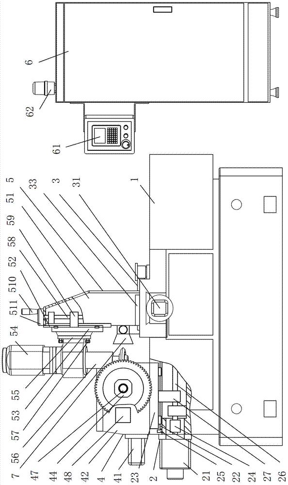
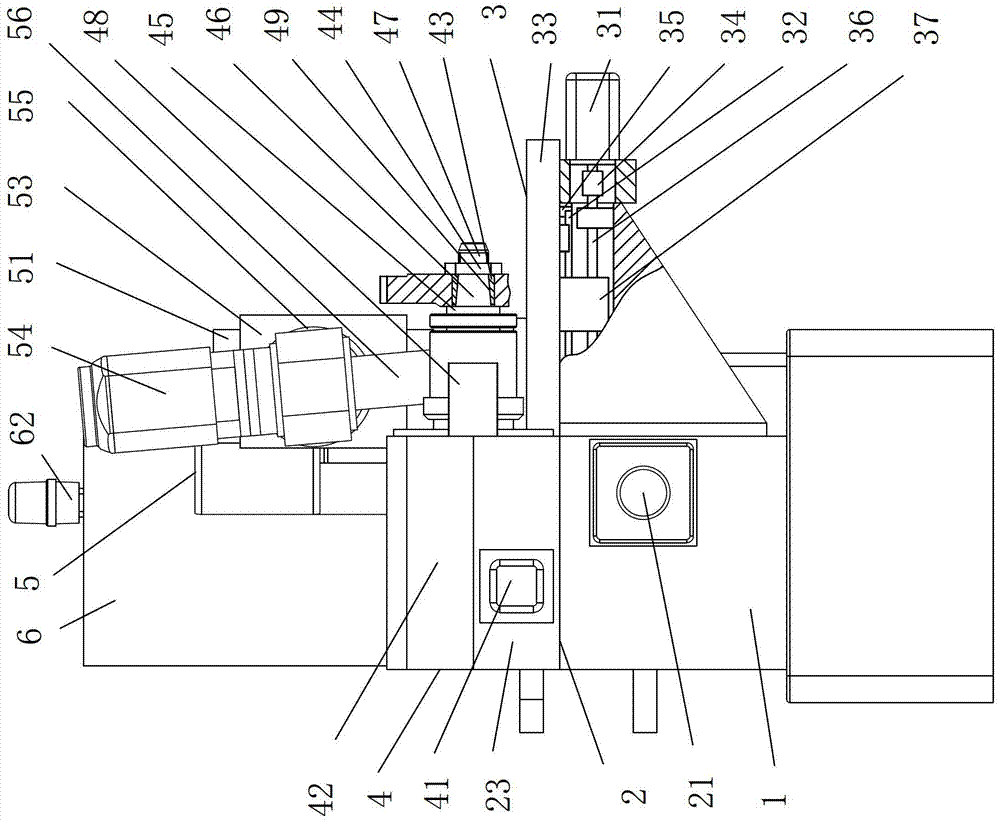
[0020] as attached figure 1 , attached figure 2 Shown: a gear edge grinding machine, including a base 1, an X-direction movement unit 2 and a Y-direction movement unit 3 respectively connected to the base 1, a gear positioning and rotating device 4 connected to the X-direction movement unit 2, and a Y-direction movement unit 4 connected to the Y-direction movement unit. The grinding device 5 and the controller 6 are connected to the movement unit 3 .

[0021] The X-direction motion unit 2 includes an X-direction servo motor 21 screwed to the base 1, an X-direction slide 23 connected to the base 1 through an X-direction linear guide 22, an X-direction ball screw, and an X-direction coupling 24 and two X-direction limit switches 25 that are opposite to one end of the X-direction slide seat 23 and are screwed to the base 1; the two ends of the X-direction screw 26 of t...


PUM


Abstract

The invention relates to the field of gear machining and aims at providing a gear edge and corner grinding machine, which comprises a base, an X-direction movement unit and a Y-direction movement unit which are respectively connected with the base, a gear positioning and rotating device which is connected with the X-direction movement unit, a grinding device which is connected with the Y-direction movement unit, and a controller. When the gear edge and corner grinding machine is used, a gear with edges and corners to be ground is installed on the gear positioning and rotating device, the controller controls the X-direction movement unit, the Y-direction movement unit, the gear positioning and rotating device and the grinding device to perform edge and corner machining to the two end surfaces of the gear with different gear end curves and six edges at the top of the gear according to a set program in a linked way. The gear edge and corner grinding machine has the advantages that the machining accuracy is better, the efficiency is higher and the adaptability to the chamfering of gears with different tooth inclinations is better.

Description

technical field [0001] The invention relates to the field of gear processing, in particular to a gear edge grinding machine. Background technique [0002] Grinding the six ridgeline chamfers on the two ends of the gear and the top of the tooth by hand is inefficient and labor-intensive; the utility model of Chinese Patent No. CN 2885475Y discloses a gear chamfer grinding equipment, which is installed by a machine base and a workpiece The electric grinding head is composed of a fixture, an electric grinding head, and an electric grinding head mounting frame. The electric grinding head is composed of a high-speed motor, a casing, a main shaft of the electric grinding head, and a bearing. The diameter of the main shaft of the grinding head is 1.5 to 2 times the diameter of the main shaft of the electric grinding head of the corresponding specification. The electric grinding head is in close contact with the cooling plate on the mounting frame of the electric grinding head to im...

Claims


Application Information

Patent Timeline
IPC IPC(8): B23F19/12
Inventor 吴寿光
Owner PINGYANG WUJING MACHINERY MFR FACTORY
Learn More