
Precision treater for condensed water

A technology for condensed water and processor, applied in chemical instruments and methods, fixed filter element filters, filtration and separation, etc., can solve the problems of wasting water, long backwashing time, long cleaning time, etc., to simplify the structure and save raw materials. Auxiliary materials, the effect of electric energy shortening

Active Publication Date: 2014-01-01
常熟市华能水处理设备有限责任公司
View PDF8 Cites 1 Cited by
  • Summary
  • Abstract
  • Description
  • Claims
  • Application Information

AI Technical Summary

Problems solved by technology

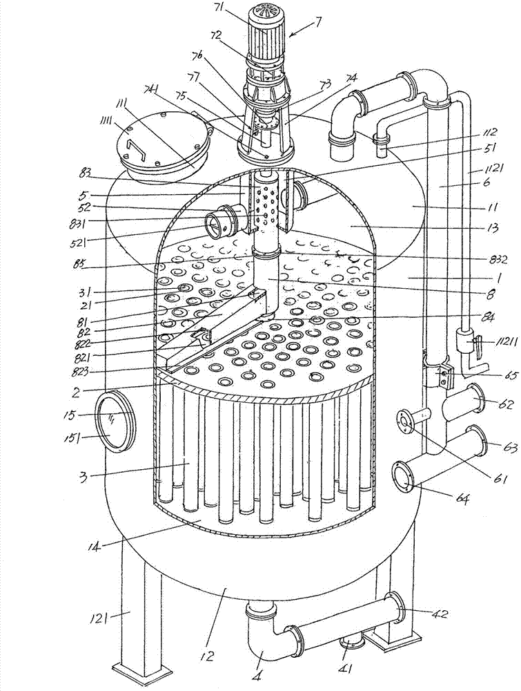
[0007] However, the backwashing mechanism equipped with the above-mentioned "filter" has the following disadvantages: one, because the backwashing liquid from the backwashing liquid outlet is first sprayed into a certain chamber of the backwashing booster chamber in a horizontal state, Then the chamber makes the backwash liquid flow downward to backwash the filter element below the chamber, so the backwash liquid outlet cannot be directly aligned with the filter element to play the backwash function, that is to say, the backwash liquid is not correct. The filter element produces a direct injection effect, so the cleaning effect on the dirt attached to the filter element is insufficient, the cleaning time is long, the water source is wasted, and the time for the filter to return to the initial working state is affected; secondly, due to the long backwashing time, it is not conducive to saving support The power consumption of the motor of the backwashing mechanism; thirdly, the structure of the backwashing synergistic chamber is relatively complicated, for example, a group of partition plates need to be set at intervals on the barrel partition plate, and the group of radially distributed The partition plate and by means of the closure of the cover plate form a plurality of backwashing synergistic chambers on the cylinder cavity partition plate, so not only the manufacture is troublesome, but also the amount of raw materials used is large

Method used


Image

  • Precision treater for condensed water
  • Precision treater for condensed water

Examples


Embodiment Construction

[0023] In order to enable the examiners of the patent office, especially the public, to understand the technical essence and beneficial effects of the present invention more clearly, the applicant will describe in detail the following in the form of examples, but none of the descriptions to the examples is an explanation of the solutions of the present invention. Any equivalent transformation made according to the concept of the present invention which is merely formal but not substantive shall be regarded as the scope of the technical solution of the present invention.

[0024] In the following descriptions, all the directional or azimuth concepts involving up, down, left, and right (including the upper end in the height direction, the lower end in the height direction, and the middle in the height direction) are aimed at the position status shown in the illustration. Therefore, it cannot be understood as a specific limitation on the solution of the present invention.

[0025...


PUM


Abstract

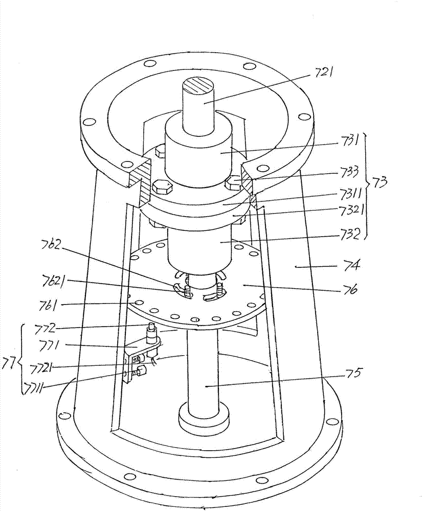
A precision treater for condensed water belongs to the technical field of water treatment equipment, and comprises a barrel, a barrel cavity partition plate, a group of lower cavity filter elements, a condensed water leading-in pipe, a spacer sleeve, a return water pipe, a back-wash pipe drive mechanism and a back-wash pipe, wherein the barrel is provided with an upper seal head and a lower seal head; the barrel cavity partition plate is arranged in a barrel cavity; a group of lower cavity filter element liquid outlet matching holes are formed in the barrel cavity partition plate; the lower cavity filter elements are arranged in the lower cavity of the barrel; the condensed water leading-in pipe is fixed with the bottom of the lower seal head; the spacer sleeve is fixed on one side of the upper seal head; a spacer sleeve water inlet connector extends from one side of the spacer sleeve; a one-way valve is arranged on the water inlet connector; one end of the return water pipe extends into the cavity of the spacer sleeve, and the other end thereof extends out of the barrel cavity; the back-wash pipe drive mechanism is arranged on the upper seal head; the upper end of the back-wash pipe extends into the cavity of the spacer sleeve, and the lower end thereof is supported in the center of the barrel cavity partition plate. The precision treater has the characteristics that a back-wash liquid spray arm is fixed at the lower end of the back-wash pipe, a spray arm opening is formed in the bottom of the back-wash liquid spray arm, the back-wash effect is ideal, the back-wash time is shortened, energy is saved, the outage time of the equipment is shortened, the structure is simplified, and the material is saved.

Description

technical field [0001] The invention belongs to the technical field of water treatment equipment, and in particular relates to a condensate polisher, which is used for the treatment of steam process condensate produced in industries such as petrochemical industry, oil refining industry, biomedicine chemical industry, power station and papermaking. Background technique [0002] The condensate mentioned above is also called condensate or surface condensate or even process condensate, accordingly, the condensate polisher mentioned above can also be called condensate polisher. Taking the chemical industry and oil refining industry as an example, a large amount of high-temperature steam is used as the energy source for heating various oil products in the production process. The steam is converted into condensed water after heat exchange, that is, from gas to liquid. If the condensed water is discharged as wastewater, it will cause a waste of precious water resources; and because ...

Claims


Application Information

Patent Timeline
Patent Type & Authority Applications(China)
IPC IPC(8): B01D29/48B01D29/52B01D29/60B01D29/68B01D35/30
Inventor 俞蓉
Owner 常熟市华能水处理设备有限责任公司
Learn More