
A phase detection and frequency multiplication logic circuit with error prevention mechanism

A logic circuit and phase detection technology, which is applied in the field of phase detection and frequency multiplication logic circuits, can solve problems such as incorrect output, delay, and precise signal noise, and achieve the effect of solving noise and delay, and preventing latch signal errors

Inactive Publication Date: 2017-01-04
CENT SOUTH UNIV
View PDF5 Cites 0 Cited by
  • Summary
  • Abstract
  • Description
  • Claims
  • Application Information

AI Technical Summary

Problems solved by technology

[0005] The technical problem to be solved by the present invention is to provide a phase-detection and frequency-multiplication logic circuit with an error prevention mechanism for the deficiencies of the existing technology, so as to solve the problem that the precise signal ignored by the existing circuit will generate noise and delay when passing through the basic phase detection module. Problem with incorrect output when starting the circuit

Method used


Image

  • A phase detection and frequency multiplication logic circuit with error prevention mechanism
  • A phase detection and frequency multiplication logic circuit with error prevention mechanism
  • A phase detection and frequency multiplication logic circuit with error prevention mechanism

Examples


Embodiment Construction

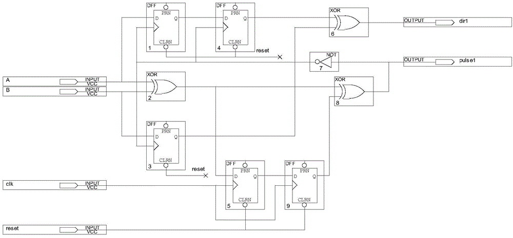
[0018] Such as figure 1 As shown, an embodiment of the present invention includes a phase detection and frequency multiplication module, and the phase detection and frequency multiplication module is connected with a phase detection signal filtering module and a frequency multiplication signal conditioning module.

[0019] The phase detection and multiplication module uses five D flip-flops, three XOR gates, and one NOT gate. The phase detection part uses three D flip-flops, one XOR gate and one NOT gate, and the frequency multiplication part uses two D flip-flops and two XOR gates. The working principle of the phase detection part is that the signal is sent to the XOR gate operation after being delayed by the D flip-flop to obtain the initial phase detection signal, and the clock signal of the D flip-flop is the reversed signal of the initial frequency multiplication signal. The working principle of the frequency multiplication part is that after the signal is processed by t...


PUM


Abstract

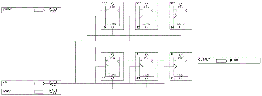
The invention discloses a phase demodulation frequency doubling logical circuit with an error-proofing mechanism. The phase demodulation frequency doubling logical circuit comprises a phase demodulation frequency doubling module, a phase demodulation signal filtering module and a frequency doubling signal conditioning module, wherein the phase demodulation frequency doubling module comprises five D flip-flops, three exclusive-OR gates and a NOT gate; the phase demodulation signal filtering module comprises three D flip-flops, three NAND gates and an exclusive-OR gate, the input ends of the phase demodulation signal filtering module receive initial phase demodulation signals, clock signals and reset signals respectively, and phase demodulation signals are output; the frequency doubling signal conditioning module comprises six D flip-flops, the input ends of the frequency doubling signal conditioning module receive initial frequency doubling signals, the clock signals and the reset signals respectively, and frequency doubling signals are output. According to the phase demodulation frequency doubling logical circuit, the initial frequency doubling signals are reversed to serve as the phase demodulation clock signals to be input, and the problem that the D flip-flops are triggered mistakenly is solved; the filtering module and the conditioning module are combined on the basis of the phase demodulation frequency doubling module, and the problems that signal glitches, time delay and incorrect output occurring when the circuit is not started are caused after accurate signals pass through the phase demodulation frequency doubling module are solved.

Description

technical field [0001] The invention relates to a phase detection and frequency multiplication logic circuit in the field of DC motor feedback systems based on data collection and processing. Background technique [0002] In the detection link of the feedback control system of the DC motor, the speed and direction of the DC motor are often detected by the photoelectric encoder. When the motor rotates, the grating disc and the motor rotate at the same time, the photoelectric encoder detects and outputs the pulse signal, and the speed and direction of the motor can be obtained by calculating and processing the pulse signal. The higher the accuracy, the more pulses per second are obtained. Optical encoders can be applied to feedback control of various motors, such as brushless DC motors (BLDC), switched reluctance motors (SRD), AC induction motors (ACIM), etc. A typical incremental photoelectric encoder usually consists of a light source (transmission module), a code disc, a ...

Claims


Application Information

Patent Timeline
Patent Type & Authority Patents(China)
IPC IPC(8): H03K5/1252
Inventor 陈鑫徐斌刘仁辉吴敏曹卫华
Owner CENT SOUTH UNIV
Learn More