
Photoelectric signal amplification circuit for photometric system

A technology of photoelectric signal and amplifying circuit, applied in the field of photometric system, can solve the problems of complex circuit structure, inability to apply photometric system with electrical signal, unable to meet various needs, etc., and achieve the effect of improving conversion efficiency and high precision

Inactive Publication Date: 2013-12-25
刘亚男
View PDF5 Cites 3 Cited by
  • Summary
  • Abstract
  • Description
  • Claims
  • Application Information

AI Technical Summary

Problems solved by technology

[0005] Existing photoelectric signal amplification circuits are composed of photoelectric conversion circuits, operational amplifier circuits, voltage comparators and gate circuits. The signal is applied to the follow-up circuit of the photometry system, which reduces the conversion efficiency of sunlight and cannot meet various needs in practical applications

Method used


Image

  • Photoelectric signal amplification circuit for photometric system
  • Photoelectric signal amplification circuit for photometric system

Examples


Embodiment Construction

[0014] In order to make the objectives, technical solutions, and advantages of the present invention clearer, the embodiments of the present invention will be described in further detail below in conjunction with the accompanying drawings.

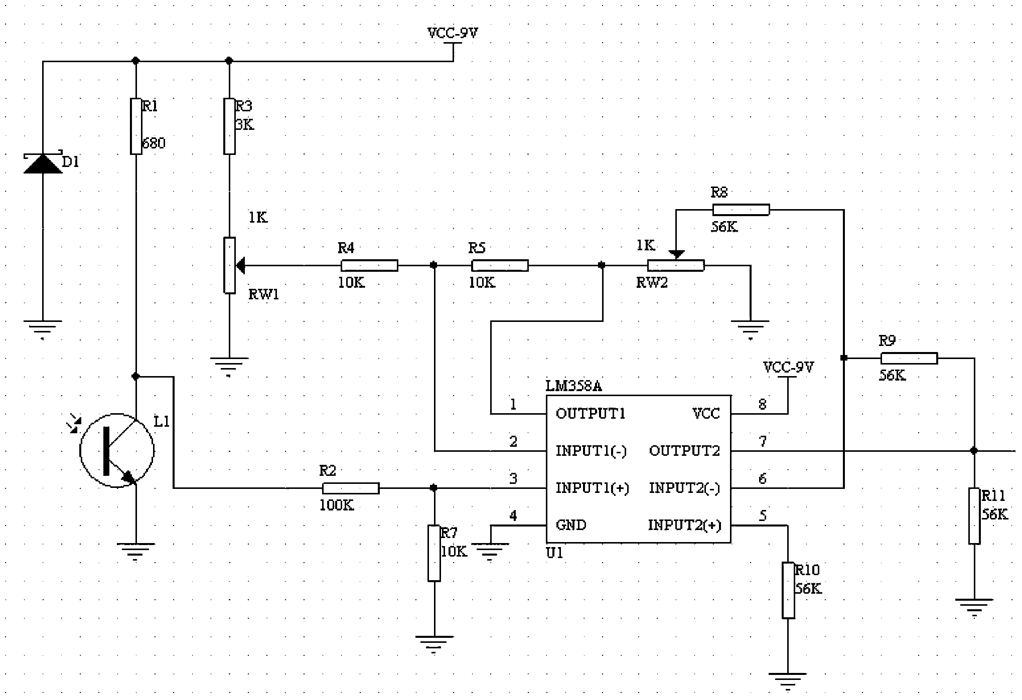
[0015] In order to improve the conversion efficiency of sunlight and reduce the complexity of the circuit, an embodiment of the present invention provides a photoelectric signal amplifying circuit used in a photometric system, see figure 1 , See the description below for details:

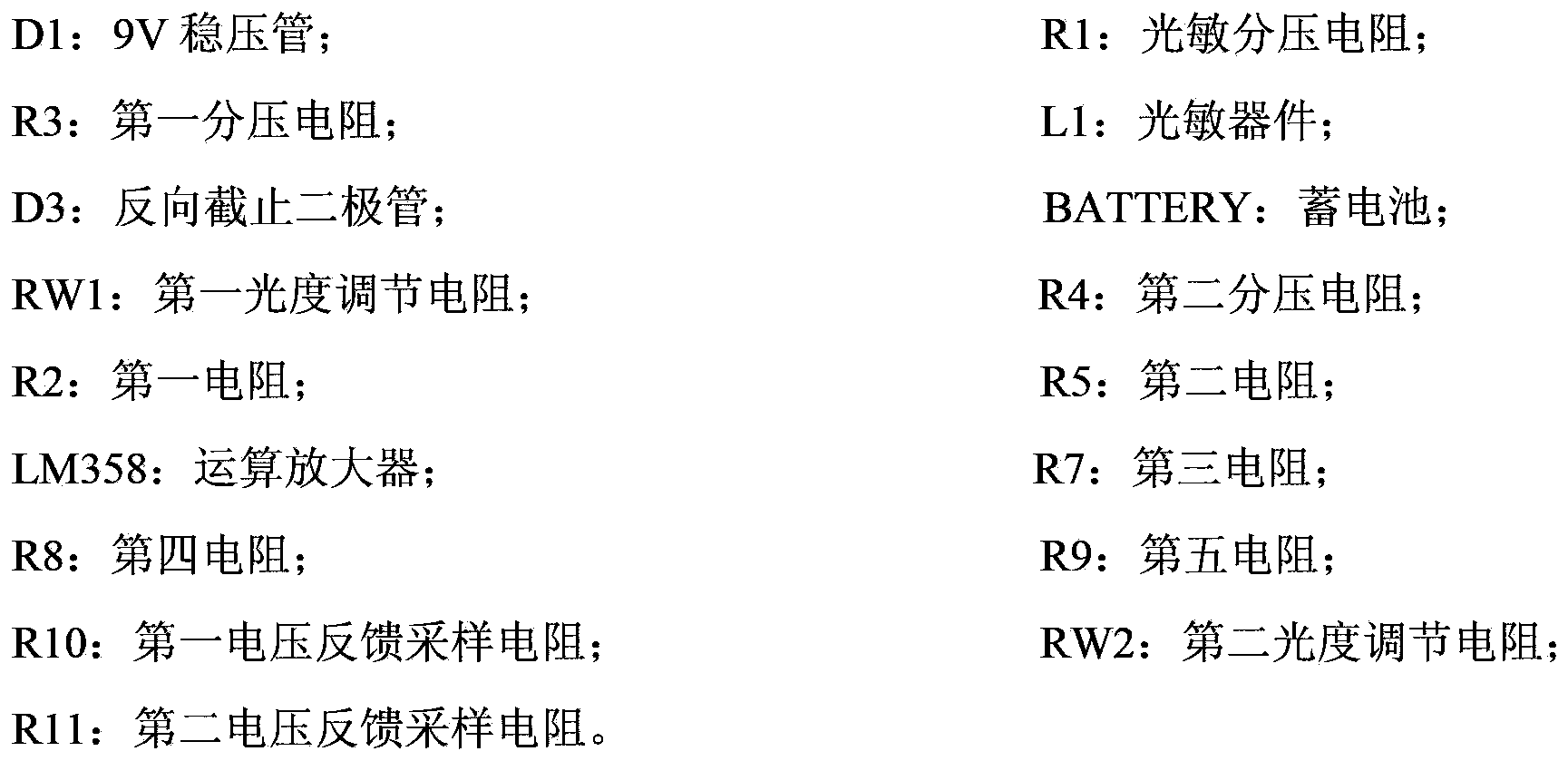
[0016] The photoelectric signal amplifying circuit includes: the anode grounded 9V voltage regulator tube D1, the cathode of the 9V voltage regulator tube D1 is connected to the photosensitive voltage divider resistor R1, the first voltage divider resistor R3 and the 9V power supply VCC, and the photosensitive voltage divider resistor R1 is connected to the photosensitive device L1 ; The first voltage divider resistor R3 is connected to the first luminosity adjusting...


PUM


Abstract

The invention discloses a photoelectric signal amplification circuit for a photometric system. A non-inverting input end of a second input pin of an operational amplifier is connected with a first voltage feedback sampling resistor, an inverting input end of the second input pin of the operational amplifier is connected with a fourth resistor and a fifth resistor, a first output pin of the operational amplifier is connected with a second luminosity adjusting resistor, the second luminosity adjusting resistor is connected with the fourth resistor, the fifth resistor is connected with a second voltage feedback sampling resistor, the second voltage feedback sampling resistor is grounded, and a second output pin of the operational amplifier outputs secondarily amplified voltage signals. According to the photoelectric signal amplification circuit, sensed sunlight is converted into the voltage signals by the aid of a phototriode, the secondarily amplified voltage signals are outputted by the operational amplifier through subsequent processing of a voltage-dividing resistor, the luminosity adjusting resistor and the operational amplifier, and the requirement of a subsequent circuit is met. By the aid of the photoelectric signal amplification circuit, sunlight conversion efficiency is improved, precision is high, and various requirements of practical application are met.

Description

Technical field [0001] The present invention relates to the field of photometric systems, in particular to a photoelectric signal amplifying circuit used in photometric systems. Background technique [0002] Due to the rotation of the earth, compared to a solar photovoltaic power generation system at a fixed location, the four seasons of spring, summer, autumn and winter, the sun rises and sets every day, and the sun's angle of illumination changes all the time, which effectively ensures that the solar panels can always face each other. The sun, the power generation efficiency will reach the best state. [0003] At present, the universal solar metering system in the world needs to calculate the angle of the sun at different times of each day of the year according to the information such as the longitude and latitude of the installation point, measure the maximum light, and convert the measured sunlight into a voltage signal. enlarge. [0004] In the process of implementing the pres...

Claims


Application Information

Patent Timeline
IPC IPC(8): H03F3/08G01J1/00
Inventor 卜凤悦
Owner 刘亚男
Learn More