
Engine Exhaust Manifolds and Flanges

An air intake flange and flange technology, which is applied to engine components, machines/engines, flange connections, etc., can solve the problems of poor coplanarity, easy resonance, air leakage and failure of split flanges, and improve the structure. Stiffness and strength, the effect of reducing local detachment and improving stress conditions

Active Publication Date: 2016-02-03
CHONGQING CHANGAN AUTOMOBILE CO LTD
View PDF7 Cites 0 Cited by
  • Summary
  • Abstract
  • Description
  • Claims
  • Application Information

AI Technical Summary

Problems solved by technology

[0005] Aiming at the technical problems existing in the prior art, the first purpose of the present invention is to provide a flange, which can effectively solve the problem of air leakage failure and loose bolts caused by the large amount of thermal deformation of the integral exhaust flange. , falling off, and can solve the problems of poor coplanarity of split flanges, concentrated prestress in bolt assembly, low structural rigidity and poor strength of manifold assembly, and easy resonance. The second purpose of the present invention is to provide a kind of Flange Exhaust Manifold Construction

Method used


Image

  • Engine Exhaust Manifolds and Flanges
  • Engine Exhaust Manifolds and Flanges
  • Engine Exhaust Manifolds and Flanges

Examples


Embodiment Construction

[0019] The present invention will be described in further detail below in conjunction with the accompanying drawings.

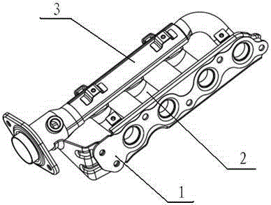
[0020] see figure 1 , the engine exhaust manifold includes a flange 1, an air channel 2, and a collecting pipe 3, wherein one end of the air channel is connected to the collecting pipe, and the other end is connected to the flange. The exhaust manifold provided by the present invention includes four air Road 2.

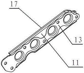
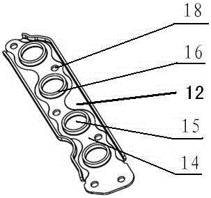
[0021] Such as figure 2 , image 3 As shown, the flange provided by the present invention includes an intake flange surface 11 connected to the cylinder head, and an air passage flange surface 12 located on the air passage side, and the flange body is provided with an air passage hole 15, so The air intake flange surface is provided with an integral convex surface 13 higher than the intake flange surface, the air passage holes 15 are distributed on the convex surface, and the flange 1 is provided with mounting holes 18, and the flange 1 passes th...


PUM


Abstract

The invention discloses a flange. The flange comprises an air inlet flange surface and an airway flange surface; the air inlet flange surface is connected with a cylinder cover; the airway flange surface is located on the airway side; the flange is provided with airway holes; the air inlet flange surface is provided with the integral convex surface which is higher than the air inlet flange surface; the airway holes are distributed in the convex surface; the flange is connected with the cylinder cover through the convex surface. The flange can effectively solve the problems of air leakage failure and bolt looseness and falling-off of an integral exhaust flange due to large thermal deformation and can solve the problems that a split type flange is poor in coplanar degree, the assembling prestress of bolts is concentrated, and the manifold assembly structure is low in stiffness, poor in strength, easy to resonate and the like. The invention also discloses an exhaust manifold structure comprising the flange.

Description

technical field [0001] The invention belongs to the technical field of engines, and in particular relates to a flange. The invention also relates to an engine exhaust manifold with the flange. Background technique [0002] The role of the engine exhaust manifold is to concentrate the exhaust gas of each cylinder of the engine into the branched pipeline of the exhaust manifold. At present, the exhaust manifold is generally connected to the cylinder head through the flange, and the flange and the Sealing gaskets are arranged between the cylinder heads, and are tightened and compressed by bolts to prevent air leakage. [0003] Exhaust manifold flanges in the prior art mainly include integral type and split type. The flange surface of the integral flange is directly in contact with the gasket, and is connected to the cylinder head through bolts. The flange of this structure has large thermal plastic deformation and large flange deformation. The contact force becomes larger or ...

Claims


Application Information

Patent Timeline
Patent Type & Authority Patents(China)
IPC IPC(8): F16L23/032F16L39/00F01N13/10
Inventor 赵艳涛戴永蓥李兵朱国兵冯敏
Owner CHONGQING CHANGAN AUTOMOBILE CO LTD
Learn More