
Safety level electric ball valve

An electric ball valve, safety-level technology, applied in valve details, valve device, valve housing structure, etc., can solve problems such as helium leakage, aggravated helium leakage, long-term operation, etc., to avoid leakage, meet external sealing requirements, meet long-term reliable results

Active Publication Date: 2013-12-25
CHINERGY CO LTD
View PDF7 Cites 9 Cited by
  • Summary
  • Abstract
  • Description
  • Claims
  • Application Information

AI Technical Summary

Problems solved by technology

However, the valve seat and the O-ring seal in the valve stem in the ball valve structure are all soft sealing materials, which are difficult to operate at high temperatures above 260°C for a long time, and the radiation resistance dose of all soft sealing materials is less than or equal to 1X10 5 Gy, while the safety ball valve on the ball flow pipeline in the fuel loading and unloading system must meet the radiation resistance dose ≥ 1×10 due to the passage of fuel balls with high radiation dose. 6 ~10 7 Gy's request
Therefore CN102606760A announces that the polyether sulfone ketone valve seat seal and the valve stem seal with O-ring used in the nuclear first-class electric ball valve announced by CN102606760A cannot be used for the safety grade ball valve on the ball flow pipeline in the fuel handling system. Special requirements for high temperature and radiation resistance
[0004] Chinese invention patent CN102734486A "a low-temperature ball valve combined sealing device" discloses a combined sealing ball valve suitable for low temperature, which adopts a bellows and a polytetrafluoroethylene elastic sealing ring valve seat to change the dynamic sealing into a static sealing to solve the internal problem of the valve. Leakage problem, at the same time, cams are set on the upper and lower valve stems to control the movement of the elastic valve seat to prolong the sealing life. The control cam is a small circle circumscribed by a square that is tangent to a large circle, and the corresponding sphere is also tangent to four vertical surfaces; other static sealing parts use O-ring seals are used. These elastic seals cannot meet the high temperature, strong radioactive and fluid helium seals. This patent also uses the valve stem packing seal, and the super-permeable helium gas can easily move from the valve stem. Seal leakage, and the wear of the valve stem on the packing under the dynamic seal and the impact of high radiation dose on the performance of the packing will further aggravate the leakage of helium

Method used


Image

  • Safety level electric ball valve
  • Safety level electric ball valve
  • Safety level electric ball valve

Examples


Embodiment Construction

[0039] In order to make the purpose, content, and advantages of the present invention clearer, the specific implementation manners of the present invention will be further described in detail below in conjunction with the accompanying drawings and embodiments.

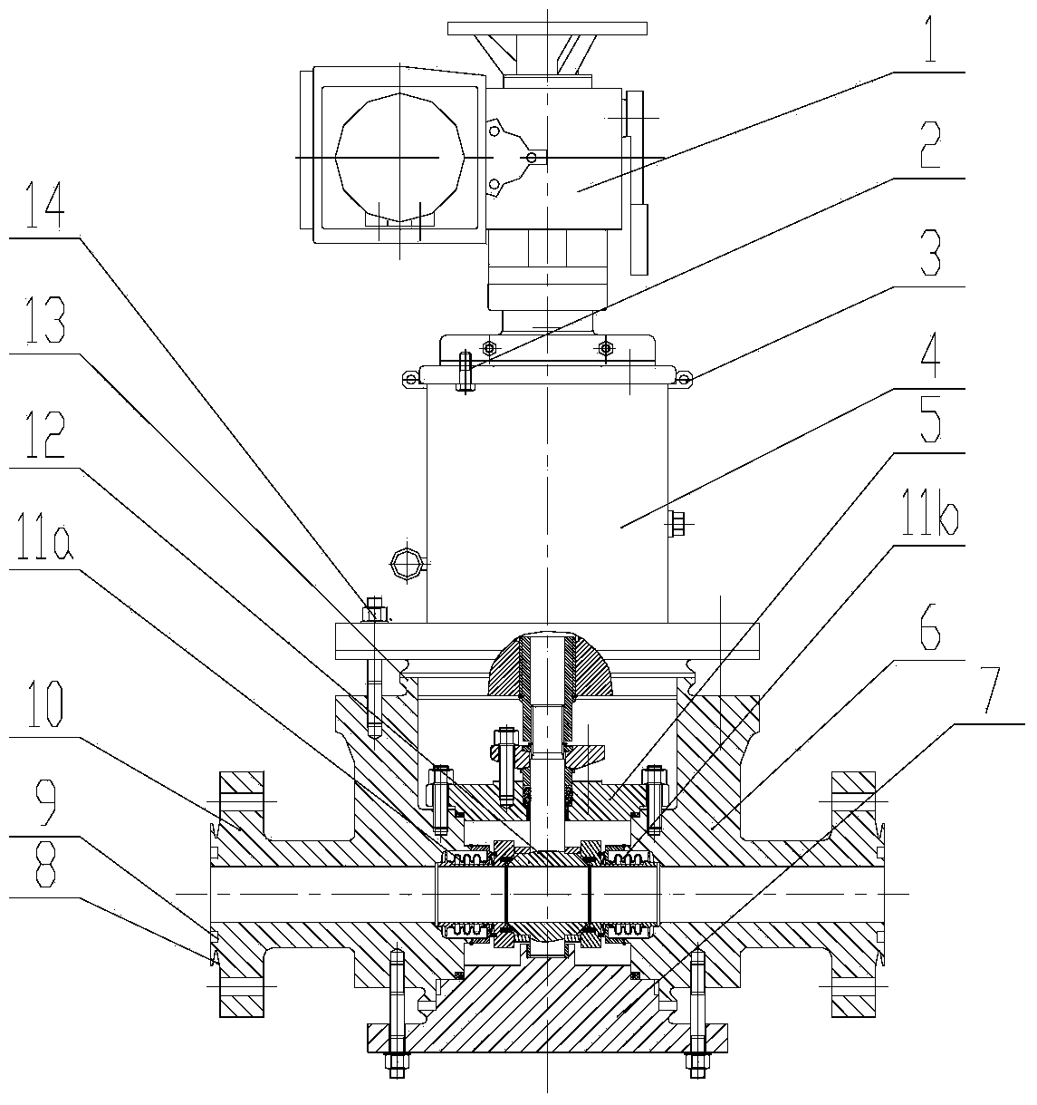
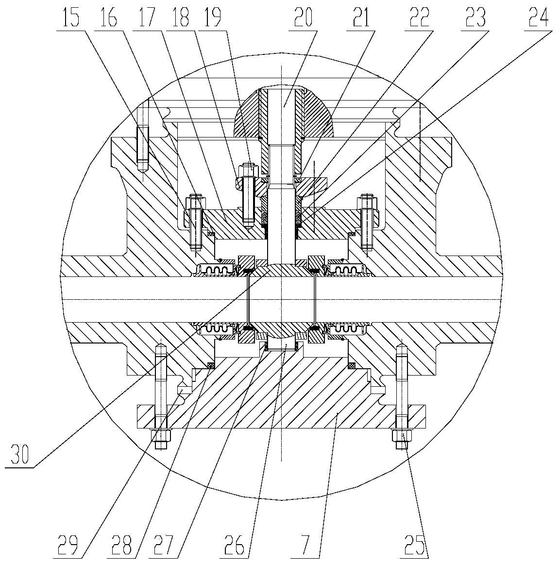
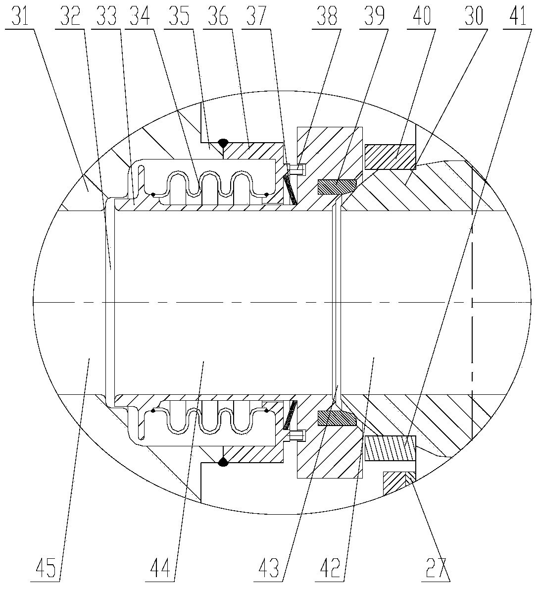
[0040] figure 1 It shows the front view of an embodiment of the pebble bed high temperature reactor safety grade electric ball valve involved in the present invention, figure 2 It is a partial view of the embodiment valve body and its internal structure, image 3 is a partial view of the implemented valve seat sealing structure, Figure 4 It is the position relationship diagram of the first cam and the sphere.

[0041] like Figure 1~3 As shown, the electric ball valve described in this embodiment is composed of a valve body 6, a left valve seat assembly 11a, a valve ball 12, a right valve seat assembly 11b, a blind flange 7, a magnetic drive 4 and an electric device 1. The valve ball 12 is composed of an upper va...


PUM


Abstract

The invention relates to the technical field of a valve, in particular to a safety level electric ball valve for a pebble-bed high-temperature reactor. The ball valve comprises a valve body, a left valve seat assembly, a valve ball, a right valve seat assembly, a blind flange, a magnetic actuator and an electric device. The electric ball valve adopting the technical scheme has the advantages that the dynamic sealing of a valve rod and a valve seat is changed into the static sealing, and the reliable sealing on high-temperature, high-pressure and high-radioactivity helium atmosphere at the pressure boundary part of the reactor in the service life of a pebble-bed high-temperature nuclear power station can be met.

Description

technical field [0001] The invention belongs to the technical field of valves, in particular to a safety electric ball valve applied to a pebble bed high temperature reactor. Background technique [0002] The pebble bed high-temperature gas-cooled reactor uses spherical fuel elements to pass through the core multiple times to achieve non-stop continuous operation. During the operation of the reactor, a certain amount of spent fuel and fuel balls that have not reached the target burnup need to be discharged from the core every day. The latter accounts for the vast majority, and needs to be transported back to the core by means of helium-carrying pneumatic force to continue reaction and recirculation. reactivity. In the fuel loading and unloading system entering and leaving the core, the first valve on the fuel ball pipeline is located at the reactor pressure boundary and belongs to the safety level valve. Different from other safety-level valves, in addition to performing t...

Claims


Application Information

Patent Timeline
Patent Type & Authority Applications(China)
IPC IPC(8): F16K5/06F16K5/08F16K5/20F16K31/04F16K41/02F16K27/06
Inventor 张海泉李红克张作义聂君锋王鑫刘继国董玉杰
Owner CHINERGY CO LTD
Learn More