
Method for increasing utilization ratio of isobutene in sulfurized isobutene production

A technology for vulcanizing isobutene and isobutene, applied in the direction of organic chemistry and the like, can solve the problems of low utilization rate of isobutene, and achieve the effects of high yield, production cost saving and low transformation cost.

Inactive Publication Date: 2013-12-25
SHENYANG GUANGDA CHEM
View PDF5 Cites 0 Cited by
  • Summary
  • Abstract
  • Description
  • Claims
  • Application Information

AI Technical Summary

Problems solved by technology

It solves the problem of low utilization rate of isobutylene in the existing atmospheric pressure method for synthesizing T321. Its structural design is ingenious, and it has the advantages of high yield, simple operation, low transformation cost, and reduced production cost of T321.

Method used


Image

  • Method for increasing utilization ratio of isobutene in sulfurized isobutene production
  • Method for increasing utilization ratio of isobutene in sulfurized isobutene production

Examples


Embodiment 1

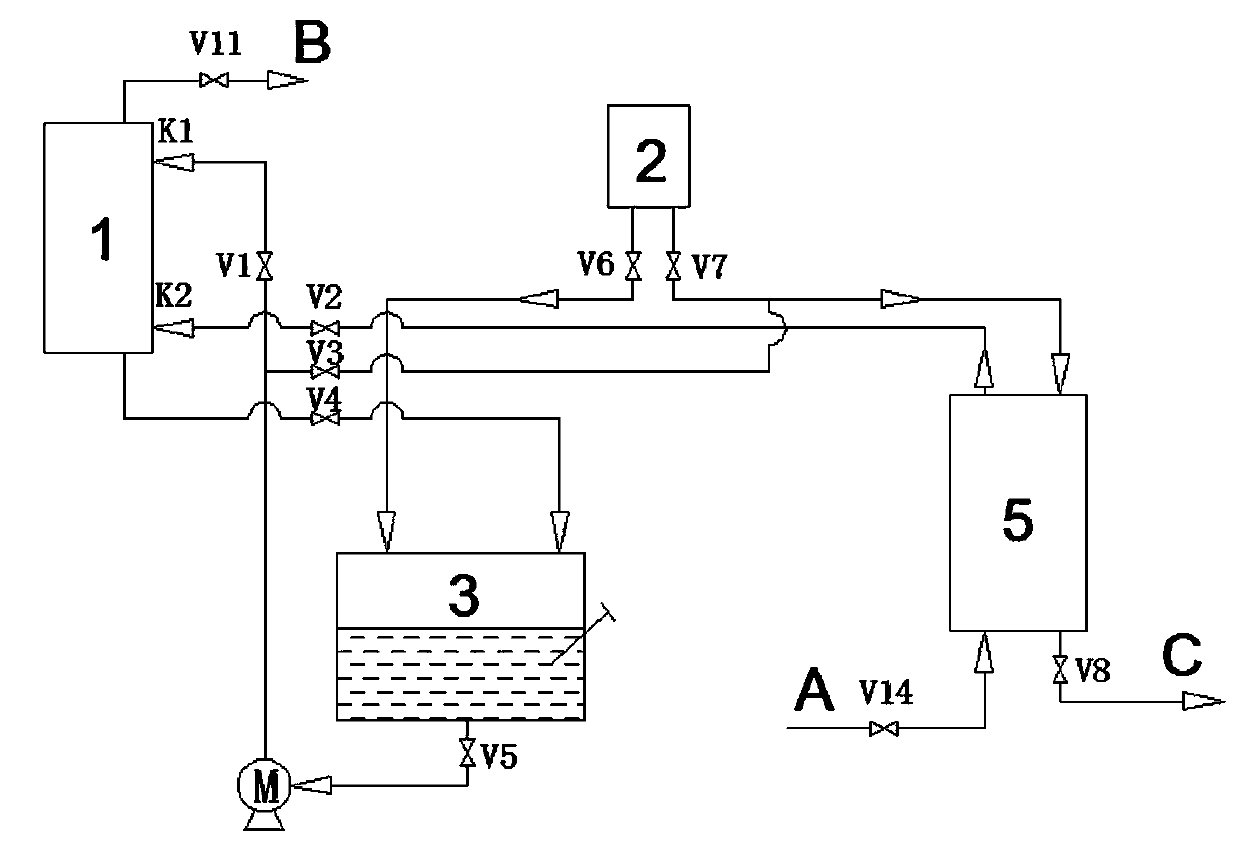
[0014] Combine below Figure 1~2 The content of the present invention is described in detail. The method for improving the utilization rate of isobutylene in the production of sulfurized isobutylene includes S 2 Cl 2 The metering tank 2, the first reaction kettle 5, the absorption tower 1, the bottom tank 3 and other parts. Among them, S 2 Cl 2 The discharge port of the metering tank 2 is connected with the feed port of the lower tank 3, and a valve V6 is set on the pipeline. The outlet of the lower tank 3 is connected to the feed end of the circulating pump M, and a valve V5 is set on the pipeline. The discharge end of the circulation pump M is connected with the feed inlet K1 at the top of the absorption tower 1, and a valve V1 is set on the pipeline. The discharge end at the bottom of the absorption tower 1 is connected to the bottom kettle 3, and a valve V4 is set on the pipeline. The top exhaust port of the absorption tower 1 is connected to the acid absorpt...

Embodiment 2

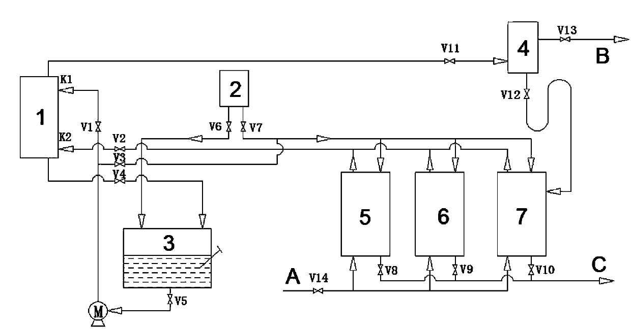
[0017] The method for improving the utilization rate of isobutylene in the production of sulfurized isobutylene includes S 2 Cl 2 Metering tank 2, first reaction kettle 5, second reaction kettle 6, third reaction kettle 7, absorption tower 1, lower tower kettle 3, gas-liquid separation device 4 and other parts. Among them, S 2 Cl 2 The discharge port of the metering tank 2 is connected with the feed port of the lower tank 3, and a valve V6 is set on the pipeline. The outlet of the lower tank 3 is connected to the feed end of the circulating pump M, and a valve V5 is set on the pipeline. The discharge end of the circulation pump M is connected with the feed inlet K1 at the top of the absorption tower 1, and a valve V1 is set on the pipeline. The discharge end at the bottom of the absorption tower 1 is connected to the bottom kettle 3, and a valve V4 is set on the pipeline. The top exhaust port of the absorption tower 1 is connected with the gas-liquid separation dev...

Embodiment 3

[0020] This embodiment optimizes embodiment 1, and 26mol% ~ 33mol% S 2 Cl 2 Pass into the lower kettle.


PUM


Abstract

The invention discloses a method for increasing a utilization ratio of isobutene in sulfurized isobutene production. The method solves the problem that the utilization ratio of isobutene in the existing non-pressure synthesis T321 method is low. The method is performed in a system comprising an S2Cl2 metering tank, a reaction kettle, an absorption tower and a lower tower kettle, wherein a discharge port of the S2Cl2 metering tank is communicated with the lower tower kettle and the reaction kettle respectively; the lower tower kettle is communicated with the upper part of the absorption tower; a circulating pump is arranged between the lower tower kettle and the absorption tower; the reaction kettle is communicated with the lower part of the absorption tower; and a bottom discharge port of the absorption tower is communicated with a feed port of the lower tower kettle. The method is ingenious in structural design, and has the advantages that the method is high in yield, simple to operate and low in reconstruction cost, and the T321 production cost is lowered.

Description

technical field [0001] The invention belongs to the field of chemical industry, in particular to a method for increasing the utilization rate of isobutylene in the production of sulfurized isobutylene. Background technique [0002] Sulfurized isobutylene extreme pressure antiwear agent, product code T321, this product has high sulfur content, good oil solubility in mineral oil, excellent extreme pressure activity and thermal stability. T321 can be compounded and used in various formulations with its chemical components, so as to be formulated into gear oils, metal processing oils, greases and anti-wear hydraulic oils that meet different specifications. [0003] In the synthetic route of atmospheric pressure method T321, the primary chlorination reaction is under atmospheric pressure, with S 2 Cl 2 Carried out with isobutene as raw material. Although the reaction process is continuously improved, the utilization rate of isobutene is always lower than 93%. The reason is th...

Claims


Application Information

Patent Timeline
IPC IPC(8): C07D341/00
Inventor 王宪法苗凤琴付志强付守法张铁华
Owner SHENYANG GUANGDA CHEM
Learn More