Design method of underwater submerged photovoltaic power generation system

A technology of photovoltaic power generation system and design method, applied in photovoltaic power generation, photovoltaic power station, photovoltaic module and other directions, can solve problems such as aquaculture disasters, outstanding problems in the field of environmental protection and aquaculture, oxygen content and temperature emission effects, etc., to reduce Environmental influences, elimination of thermal drift effects, improved effects of cleaning problems

Inactive Publication Date: 2019-01-01
HOHAI UNIV CHANGZHOU
View PDF8 Cites 0 Cited by
  • Summary
  • Abstract
  • Description
  • Claims
  • Application Information

AI Technical Summary

Problems solved by technology

[0002] At present, a floating photovoltaic power generation system has appeared on the water surface. Because the water surface is cheaper than the land, its development momentum is rapid. However, with the vigorous development of water surface photovoltaics, it is found that there are many problems, especially in the fields of environmental protection and aquaculture. protrude
For example, the floating photovoltaic power generation system uses the buoyancy tank floating on the water surface as the buoyancy carrier, but the buoyancy tank floating on the water surface occupies a large amount of water surface, reduces the contact area between the water surface and the air, and has a negative effect on the oxygen content and temperature emission in the water. In addition, the surface of photovoltaic modules of floating photovoltaic power plants is prone to dust accumulation, and excessive dust accumulation will affect the photoelectric conversion efficiency of photovoltaic modules

Method used


Image

  • Design method of underwater submerged photovoltaic power generation system
  • Design method of underwater submerged photovoltaic power generation system
  • Design method of underwater submerged photovoltaic power generation system

Examples


Embodiment

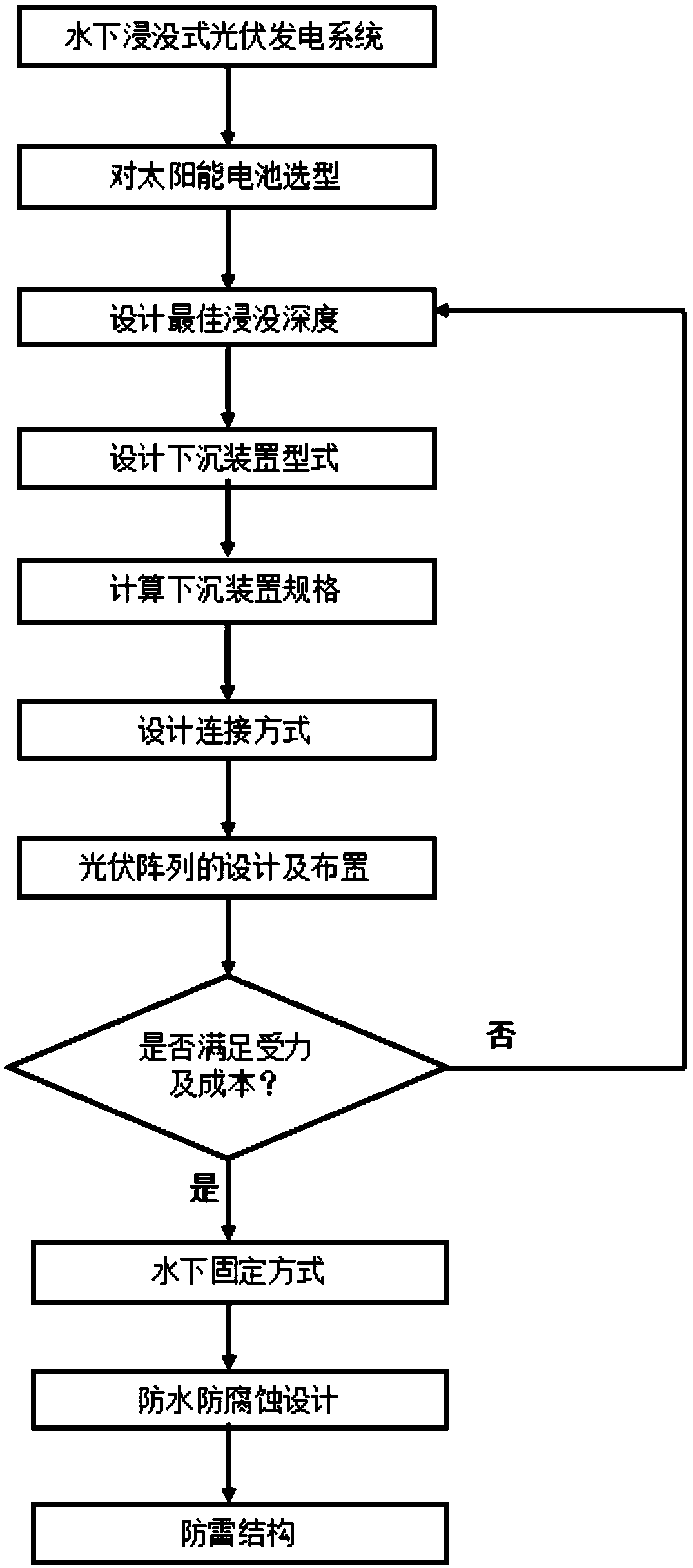
[0043] Example: Design a 30kW underwater submerged photovoltaic power generation system in a lake.

[0044] Assuming that the photovoltaic utilization hours of the photovoltaic system are about 300 hours, it can be seen that the power generation system has a small capacity and a small footprint. If it is placed in the middle of the photovoltaic array, the income will be less than the cost. On the shore of the lake. When designing the optimal immersion depth, the lake is a freshwater body, with 1cm as the step value, to ensure that the gain due to lower temperature can largely overcome the small loss caused by radiation absorption, and analyze the relationship between immersion depth and power generation It can be seen that when the immersion depth is within 15cm, the energy value of the PV module increases. By selecting a photovoltaic panel to conduct a test experiment in this lake and recording the power generation, the optimal immersion depth of the water layer can be obtain...


PUM


Abstract

The invention discloses a design method of an underwater submerged photovoltaic power generation system, which comprises the following steps: (1) selecting a solar module battery and determining the relative positions of a miniature inverter and a transformer; (2) considering the influence of water on solar radiation, designing the optimal immersion depth of solar module in water; (3) designing the sinking device for a submerged photovoltaic power generation system; (4) calculating the size and shape of the sinking device according to the required buoyancy and the design requirements of the cable trench; (5) designing the connection mode between the sinking device and the sinking device, the sinking device and the bracket, the bracket and the photovoltaic module; (6) designing and laying aphotovoltaic array, and planning a cable passage and a maintenance passage according to the geographic condition of local water area; (7) designing the fixing mode of the system in water; (8) performing the waterproofing and corrosion protection design of the system; and (9) designing the lightning protection structure of the photovoltaic system.

Description

technical field [0001] The invention relates to a design method of an underwater submerged photovoltaic power generation system, belonging to the technical field of photovoltaic power generation. Background technique [0002] At present, a floating photovoltaic power generation system has appeared on the water surface. Because the water surface is cheaper than the land, its development momentum is rapid. However, with the vigorous development of water surface photovoltaics, it is found that there are many problems, especially in the fields of environmental protection and aquaculture. protrude. For example, the floating photovoltaic power generation system uses the buoyancy tank floating on the water surface as the buoyancy carrier, but the buoyancy tank floating on the water surface occupies a large amount of water surface, reduces the contact area between the water surface and the air, and has a negative effect on the oxygen content and temperature emission in the water. I...

Claims


Application Information

Patent Timeline
Patent Type & Authority Applications(China)
IPC IPC(8): B63B35/44B63B43/14B63B43/06B63B21/50H02S10/00
CPCB63B21/50B63B35/44B63B43/06B63B43/14B63B2021/505B63B2035/4453H02S10/00Y02E10/50
Inventor 樊辰白建波王跃曹飞刘升还新新吴鹏兰康
Owner HOHAI UNIV CHANGZHOU
Why Eureka
Try Eureka