Automatic screw rod cleaning device

A self-cleaning, screw technology, applied in cleaning methods and utensils, cleaning methods using tools, chemical instruments and methods, etc., can solve the problems of plastic shovel knocking difficulties, increased work intensity, high cost, etc., to avoid hardness reduction, reduce High labor intensity and high work efficiency

Active Publication Date: 2013-12-25
TIANJIN KINGFA NEW MATERIAL +1
View PDF4 Cites 16 Cited by
  • Summary
  • Abstract
  • Description
  • Claims
  • Application Information

AI Technical Summary

Problems solved by technology

[0004] The above are the methods currently in use or existing, which can achieve the function of cleaning, but there are the following disadvantages: Method 1. The special material is expensive and used for one-time use, so the cost is high; and after the screw is cleaned, it needs to be cleaned at the production site. Clean up used washing materials, which not only increases work intensity, but also risks contamination on site
Method 2. In the cold state of the screw at room temperature, it is difficult to tap the attached plastic shovel, it takes a long time, the labor intensity is high, and the screw is easy to be damaged
At the same time, the wire wheel used for cleaning is consumed quickly and needs to be replaced frequently, which will increase the cleaning cost
Method 3. Working with open flames with hand-held tools has a high safety risk; when the attachments are burned, the smoke and other pollution are relatively large, which is likely to affect human health; it is also easy to reduce the local hardness of the screw due to uneven heating; and the consumption of liquefaction The gas consumption is large, which increases the cleaning cost
Method 4. The heating of the oil tank needs to maintain the oil temperature in the oil tank for a long time, so the energy consumption is very large, and when dealing with long screws (extruder screws can generally reach 2.5 meters and above), a large oil tank is required, so the energy consumption is greater and less expensive. Safe, but it is inconvenient to clean up if the attachment falls in the oil tank

Method used


Image

  • Automatic screw rod cleaning device
  • Automatic screw rod cleaning device
  • Automatic screw rod cleaning device

Examples


Embodiment

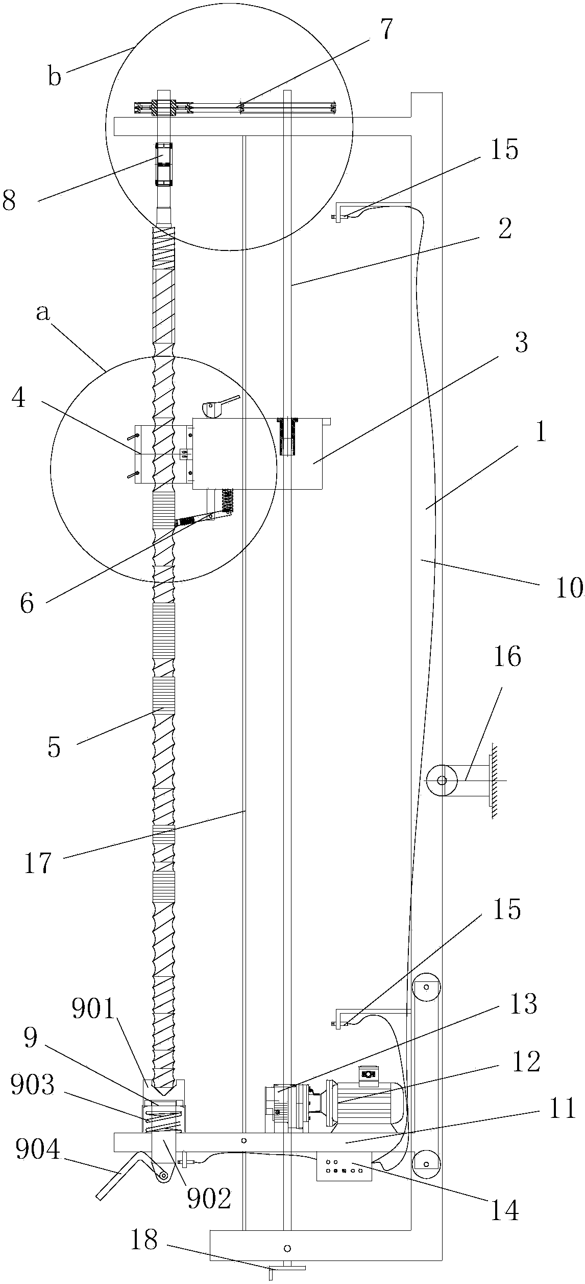
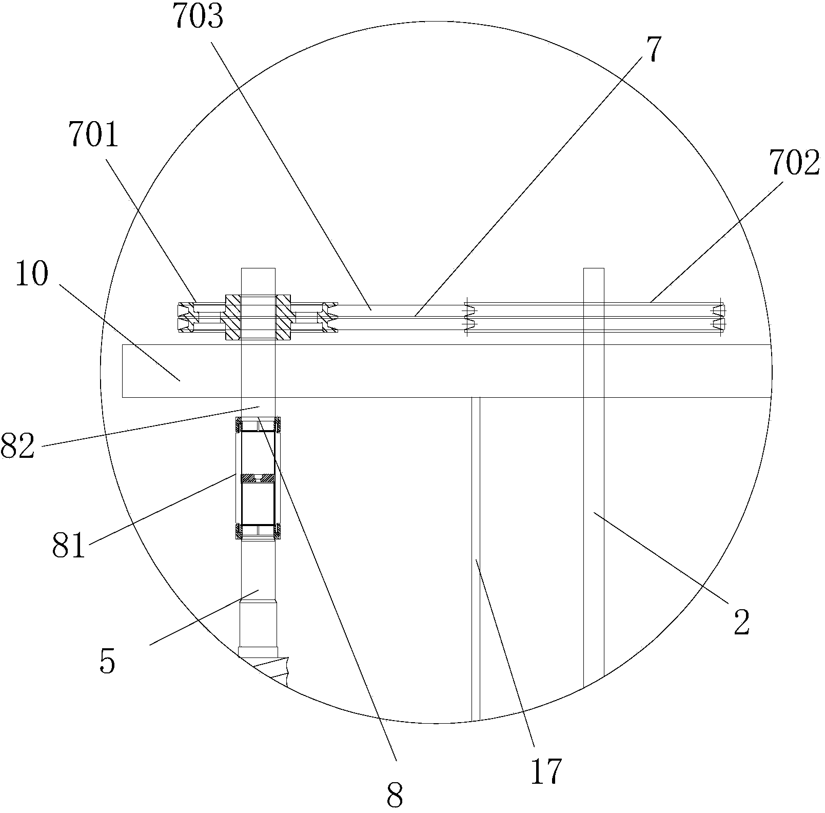
[0030] Such as Figure 1 to Figure 3 A kind of screw automatic cleaning device shown, comprises the cleaning rack 1 that is used for clamping screw rod 5, screw mandrel 2, mobile workbench 3 and heating ring 4, and the two ends of described screw mandrel 2 are installed on the two ends of cleaning rack 1 One end of the mobile worktable 3 is installed on the screw rod 2, and the heating ring 4 is fixed on the other end of the mobile workbench 3; Pass. Specifically, such as Figure 4 and Figure 5 As shown, the heating ring 4 is preferably an infrared heating ring. The heating ring 4 is mainly composed of two main bodies with a semicircular cross-section, one end of the two main bodies is connected together by a bolt 19, and the other end is fixed on the other end of the mobile workbench.

[0031]In order to further improve the cleaning effect, such as figure 2 As shown, the other end of the mobile workbench 3 is provided with a scrubbing mechanism 6, and the scrubbing mec...


PUM


Abstract

The invention discloses an automatic screw rod cleaning device. The automatic cleaning device comprises a cleaning frame, a lead screw, a moving worktable and a heating ring, wherein the cleaning frame is used for clamping a screw rod, two ends of the lead screw are mounted on two ends of the cleaning frame, one end of the moving worktable is mounted at the lead screw, and the heating ring is fixedly arranged on the other end of the moving worktable and is penetrated by the screw rod. According to the automatic screw rod cleaning device, the heating ring is utilized for cleaning the screw rod, and the automatic screw rod cleaning device is good in screw rod cleaning effect, high in efficiency, low in energy consumption, use cost and noise and high in security; the operational labor intensity is alleviated, and fused materials are low in pollution so as to be recycled.

Description

technical field [0001] The invention relates to a cleaning device, in particular to a screw automatic cleaning device. Background technique [0002] In the plastics industry, extruders and injection molding machines are widely used. These devices modify or shape plastics through the compression, conveying, shearing and other functions of the screw. When changing the material, the former material will stick to the screw, and the screw needs to be cleaned to avoid contamination of the product. [0003] At present, there are several ways to clean the screw: 1. Rinse with special washing machine material; 2. Use an angle grinder to install a steel wire wheel to grind after preliminary scraping with metal tools; 3. Burn manually with a blowtorch such as liquefied gas. ; 4. Use the oil tank heating method to clean the screw device. [0004] The above are the methods currently in use or existing, which can achieve the function of cleaning, but there are the following disadvantag...

Claims


Application Information

Patent Timeline
Patent Type & Authority Applications(China)
IPC IPC(8): B29C45/17B29C47/08B08B1/00
Inventor 刘炜李东陈智敏张智宋晓东王海蛟陶四平
Owner TIANJIN KINGFA NEW MATERIAL
Why Eureka
Try Eureka