
Machining process of multiple frame and panel combined parallel shaft gear box body

A technology of parallel shafts and frames, which is applied in the field of processing of multi-frame panel combined parallel shaft gearboxes, can solve the problems of extended processing cycle, high processing cost, high processing equipment specifications and precision requirements, and ensure design accuracy , avoid processing waste products, and ensure the effect of the production cycle

Inactive Publication Date: 2013-12-25
ZHENGZHOU RES INST OF MECHANICAL ENG CO LTD
View PDF3 Cites 17 Cited by
  • Summary
  • Abstract
  • Description
  • Claims
  • Application Information

AI Technical Summary

Problems solved by technology

The more the frame panel group, the larger the total span of the bearing hole, so the disadvantages of processing this kind of box according to the traditional processing technology are: 1. It needs multiple clamping to complete the processing of the bearing hole, which is time-consuming and laborious, and the accuracy is difficult to guarantee , especially for single-piece small-batch production and processing costs are high; 2. The specifications and accuracy of processing equipment are high. Generally, small and medium-sized processing enterprises do not have large-scale high-precision CNC machining centers, and outsourcing processing increases transportation and processing costs. It also prolongs the processing cycle; 3. The length and rigidity of the general boring tool bar cannot guarantee the machining accuracy, and the tool bar needs to be specially customized, which also increases the production cost and prolongs the processing cycle

Method used


Image

  • Machining process of multiple frame and panel combined parallel shaft gear box body
  • Machining process of multiple frame and panel combined parallel shaft gear box body
  • Machining process of multiple frame and panel combined parallel shaft gear box body

Examples


Embodiment Construction

[0025] The present invention is further described with the manufacturing process of the gear box body consisting of two frames and three panels:

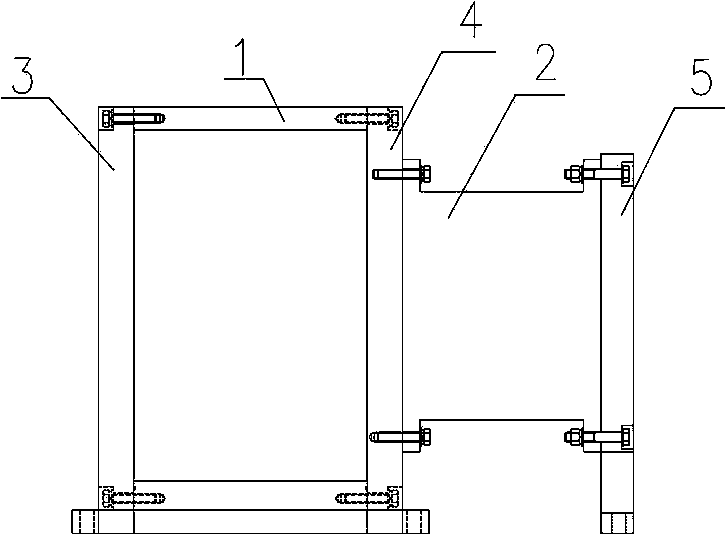
[0026] Such as Figure 1-6 , Figure 1.1 As shown, the box body of the gear box is assembled and fixed together with the first frame 1 and the second frame 2 by the first panel 3 , the second panel 4 and the third panel 5 through positioning pins and bolts. Specifically: the first panel 3 and the second panel 4 are assembled and fixed on opposite sides of the first frame 1, figure 2 , 3 , 5 form a frame panel group; one side of the second frame 2 is assembled and fixed with the second panel 4 by bolts, and the other side of the second frame 2 is assembled and fixed with the third panel 5 by bolts and positioning pins, image 3 , 4 , 6 to form another frame panel group; the first panel 3, the second panel 4, and the third panel 5 are respectively provided with a plurality of bearing seat holes on the board surface; on the ba...


PUM


Abstract

The invention discloses a machining process of a multiple frame and panel combined parallel shaft gear box body. The machining process includes that step 1, panel combined parts and frame combined parts of the box body are machined separately according to the design drawing; when panels and frames are machined, the panels are milled first, then bearing seat holes are bored, and bolt holes and positioning pin holes are drilled at last; the positioning pin holes which are formed in the panels are drilled into positioning pin holes for preassembly when being machined, the diameter of the positioning pin holes for the preassembly is smaller than the size of the design drawing, and the positioning pin holes are to be assembled and reamed in step 3 and drilled and reamed to meet the requirements of the size of the design drawing in step 4; step 2, pin shafts are assembled according to the box body bearing seat holes in the design drawing; step 3, gear shaft systems are replaced by the pin shafts which are assembled in the step 2 according to the design drawing to preassemble frame assemblies and panel assemblies and connecting bolt holes which are formed in the combined surfaces of the frame assemblies and the panel assemblies are assembled and drilled and the positioning pin holes for the preassembly are assembled, drilled and reamed; step 4, the box body which is preassembled in the step 3 is disassembled, the pin shafts which are matched with the bearing seat holes are taken out, and gear shafts and bearing parts are assembled in the box body. The machining process of the multiple frame and panel combined parallel shaft gear box body has the advantage of saving the cost.

Description

technical field [0001] The invention relates to a multi-frame panel combined parallel shaft gearbox, in particular to a processing technology for a multi-frame panel combined parallel shaft gearbox body. Background technique [0002] A gear box is a power transmission device that realizes functions such as speed change (increase and deceleration), distance change, and direction change between the prime mover and the working machine. It is generally composed of gears, shafts, bearings, boxes supporting it, and other accessories. The assembly process of the general gearbox is: after the parts such as gears, shafts and bearings are assembled, they are then assembled in the bearing seat holes of the box body. The box body has integral type and combined type, and the box body is commonly combined: some boxes are cut from the center line of the bearing seat hole, and the upper, middle, and lower parts are longitudinally superimposed and combined; some box bearing seat holes are co...

Claims


Application Information

Patent Timeline
IPC IPC(8): B23P15/00
Inventor 李丽霞李培军张金龙陈亮白柑秋李云鹏敖宝林程自力
Owner ZHENGZHOU RES INST OF MECHANICAL ENG CO LTD
Learn More