
Automobile optical fiber illumination engine

An optical fiber lighting and automotive technology, applied in the field of automotive lighting systems, can solve the problems of the light source being affected by the lamp body, energy consumption, hidden danger of spontaneous combustion of cables, etc. Effect

Inactive Publication Date: 2013-12-18
LANZHOU GEELY AUTOMOBILE IND +1
View PDF8 Cites 0 Cited by
  • Summary
  • Abstract
  • Description
  • Claims
  • Application Information

AI Technical Summary

Problems solved by technology

[0006] The purpose of the present invention: first, to solve the problem that the light source of the existing automobile lighting system is affected by the lamp body; energy consumption and the hidden danger of spontaneous combustion of cables

Method used


Image

  • Automobile optical fiber illumination engine
  • Automobile optical fiber illumination engine
  • Automobile optical fiber illumination engine

Examples


Embodiment 1

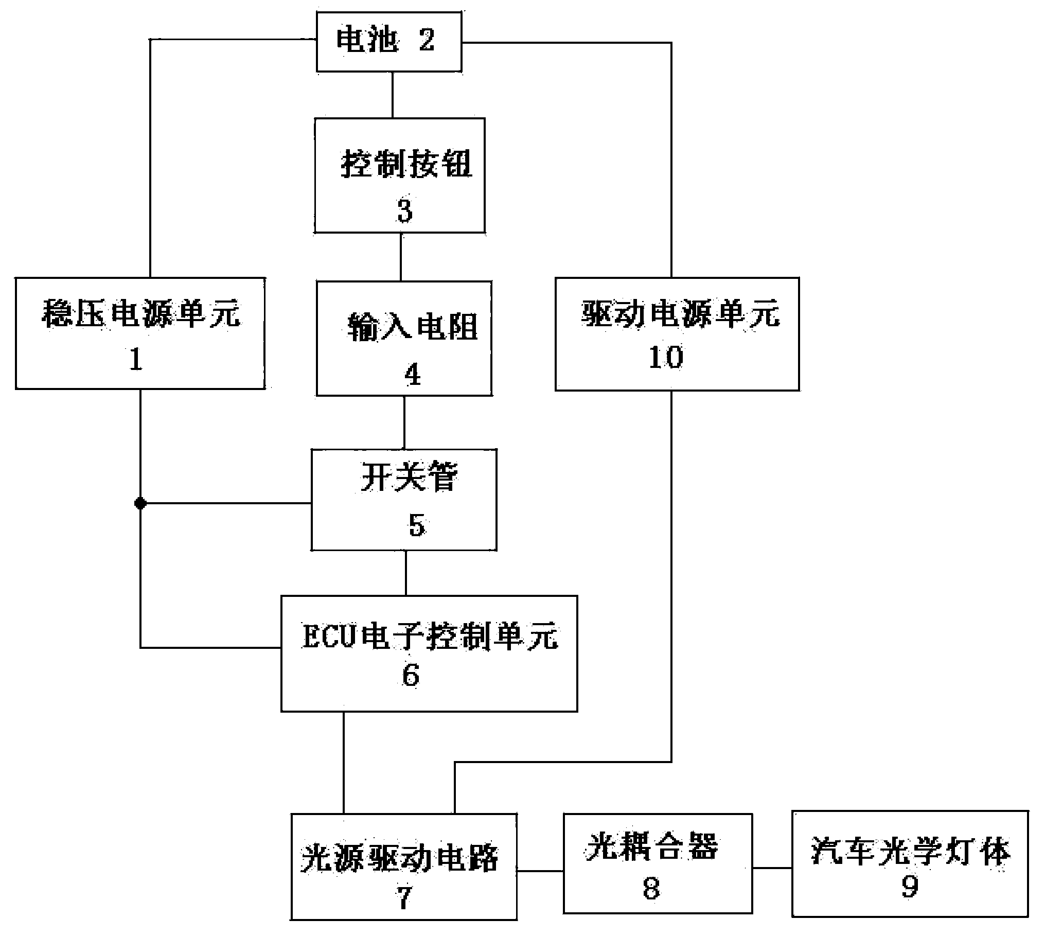
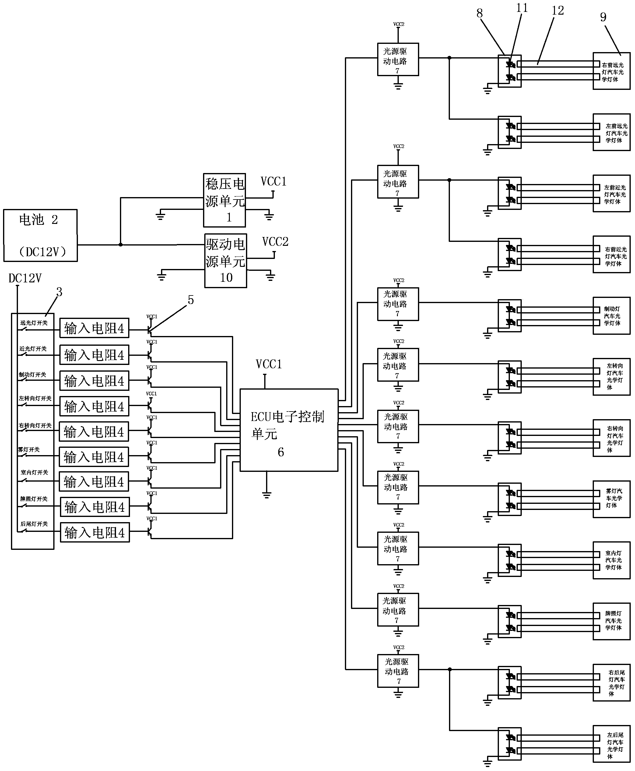
[0032] Embodiment one: a kind of automobile optical fiber lighting engine, such as figure 1 , figure 2 As shown, it includes a battery 2, a regulated power supply unit 1, a drive power supply unit 10, several mutually independent control buttons 3, several mutually independent input resistors 4, several mutually independent switch tubes 5, a ECU Electronic control unit 6, several mutually independent light source driving circuits 7, several mutually independent optical couplers 8, several optical fibers 12 and several mutually independent automotive optical lamp bodies 9, wherein, ECU The electronic control unit includes several signal input interfaces and several signal output interfaces; the battery is connected to the electrical input terminal of the regulated power supply unit, the battery is connected to the electrical input terminal of the driving power supply unit, and the front end of the control button is connected to the battery; the input resistance The number is...

Embodiment 2

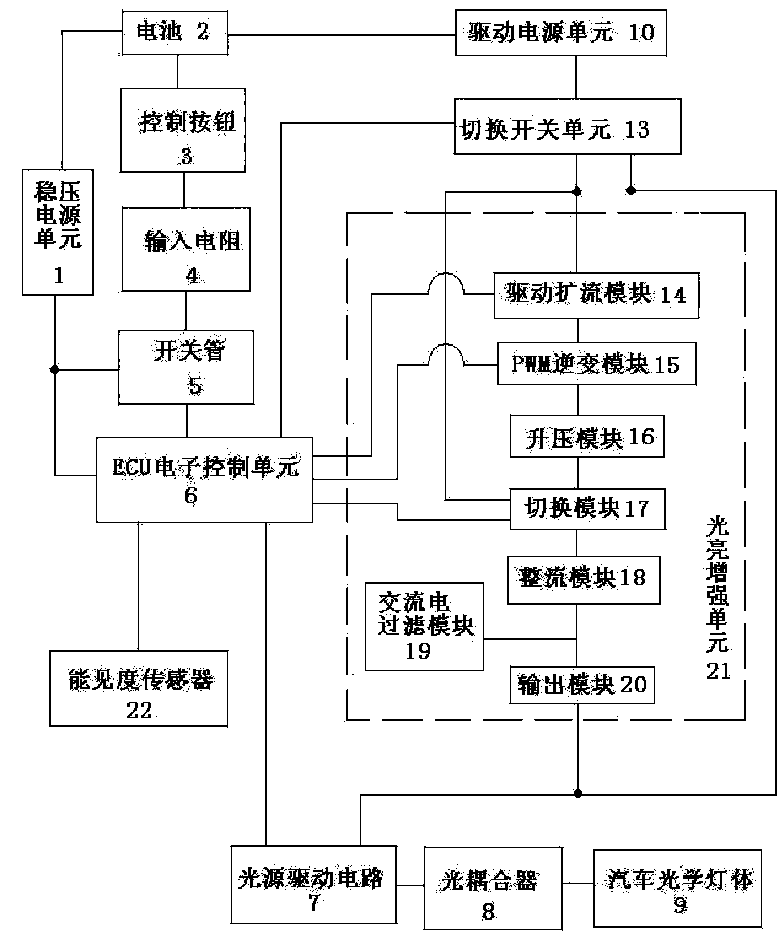
[0034] Embodiment two, see image 3 , Figure 4 , Figure 5 , Figure 6 , Figure 7 , Figure 8 As shown, the second embodiment adds the visibility sensor 22, the switching unit 13 and the light enhancement unit 21 on the basis of the first embodiment. Specifically, the visibility sensor 22 is used to measure the visibility of the air. The function of the switch unit 13 is to switch and select the DC input mode of the light source drive circuit under the instruction of the ECU electronic control unit, specifically to switch and select the DC output after the drive power unit, and to switch the selected DC or directly Sending to the electrical input of the light source driving circuit, or directly feeding to the electrical input of the drive expansion module of the brightness enhancement unit, there are only two options, and only one of the two options can be selected at the same time. The function of the light enhancement unit 21 is to provide the light source driving ci...


PUM


Abstract

The invention discloses an automobile optical fiber illumination engine which is stable and reliable and achieves central control over light sources. The automobile optical fiber illumination engine comprises a battery, a stabilized voltage supply unit, a driving power supply unit, control buttons, input resistors, switching tubes, an ECU, light source drive circuits, optical couplers, optical fibers and automobile optical lamp bodies. The stabilized voltage supply unit, the driving power supply unit and the control buttons are respectively connected with the battery, the input resistors are connected with the control buttons, the switching tubes are connected with the stabilized voltage supply unit, the ECU and the input resistors respectively, the ECU, the driving power supply unit and the optical couplers are electrically connected with the light source drive circuits respectively, and the automobile optical lamp bodies are connected with the optical couplers. The automobile optical fiber illumination engine is mainly used in the technical field of illuminating systems.

Description

technical field [0001] The invention relates to the technical field of automotive lighting systems, in particular to an automotive optical fiber lighting engine. Background technique [0002] With the rapid development of the automobile industry and the continuous improvement of automobile users' requirements for automobile products. Automotive design places higher and higher demands on automotive lighting. The quality of automotive lighting is crucial to driving safety. The laws and regulations of various countries in the world today have strict requirements on automotive lighting. The design of lamps must not only meet the safety requirements such as light pattern distribution, but also some other requirements, such as the appearance should be integrated with the appearance of the entire car, beautiful and practical, and meet the requirements of aerodynamics, so that the driver And passengers feel comfortable and convenient, so the current car lamp design technology is a...

Claims


Application Information

Patent Timeline
IPC IPC(8): H05B37/02B60Q1/00
Inventor 刘关韩悌明刘禄章王晶董玲俊张磊
Owner LANZHOU GEELY AUTOMOBILE IND
Learn More