
A signal conditioning circuit

A signal conditioning circuit and positive signal technology, applied in the direction of signal transmission system, electrical signal transmission system, electrical components, etc., can solve the problems of system linearity and noise degradation, precision amplification, and reduce work efficiency, etc., to achieve the elimination of common mode Effects of Noise and Temperature Drift, Reduced Sampling Noise, and High Common-Mode Rejection Ratio

Active Publication Date: 2017-02-22
陕西海泰电子有限责任公司
View PDF4 Cites 0 Cited by
  • Summary
  • Abstract
  • Description
  • Claims
  • Application Information

AI Technical Summary

Problems solved by technology

[0002] At present, under normal circumstances, the AD acquisition chip will have high-frequency sampling noise, which will affect the preamplifier circuit, which will amplify the accuracy and deteriorate the linearity and noise of the system. Generally, a capacitor is placed close to the AD to average the current pulse. Reflection and oscillation; while the general high-precision operational amplifier can only drive a few hundred pF of capacitance; therefore, the commonly used conditioning circuit cannot meet the needs of the work, greatly reducing the efficiency of the work

Method used


Image

  • A signal conditioning circuit
  • A signal conditioning circuit
  • A signal conditioning circuit

Examples


Embodiment Construction

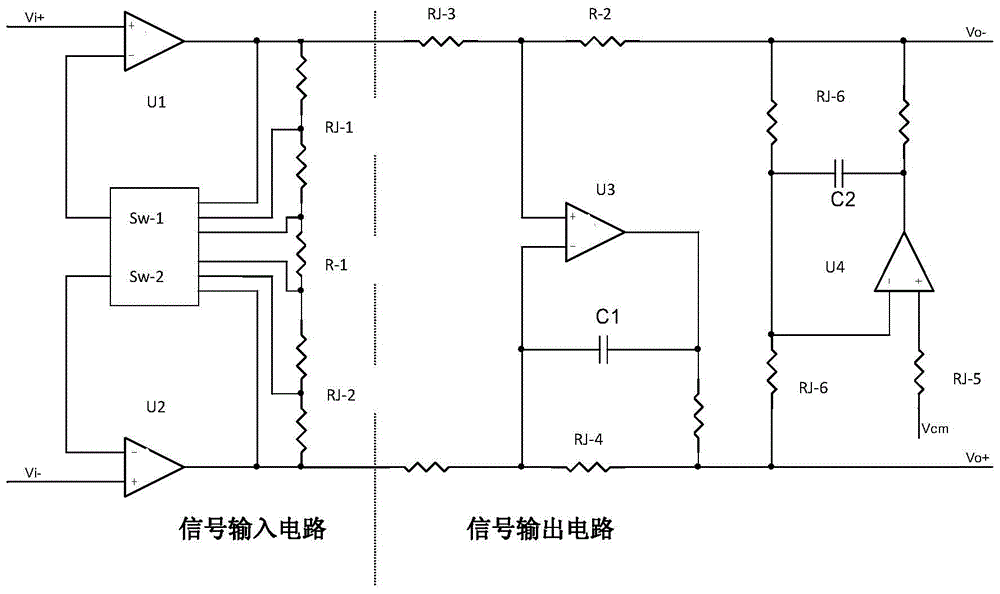
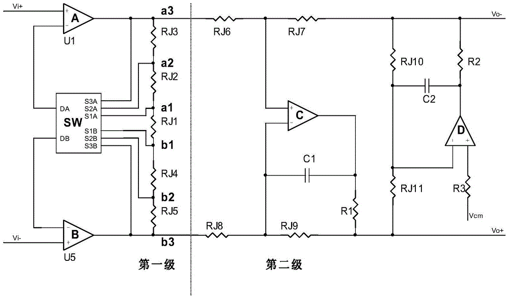
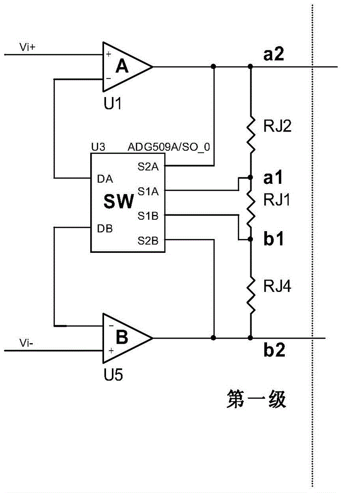
[0017] see figure 1 , the present invention provides a signal conditioning circuit, including a signal input circuit and a signal output circuit; the signal input circuit includes a positive signal input unit, a negative signal input unit and a first intermediate resistor R-1; the positive signal input unit includes a positive signal amplifier U1 , positive signal switch SW-1 and positive signal resistance unit; negative signal input unit includes negative signal amplifier U2, negative signal switch SW-2 and negative signal resistance unit; positive signal resistance unit includes N positive signal resistance RJ- 1. The positive signal switching switch SW-1 includes N+1 input terminals and one output terminal; the negative signal resistance unit includes N negative signal resistors RJ-2 connected in series; the negative signal switching switch SW-2 includes N+1 input terminals N is an integer greater than or equal to 1; one end of the positive signal resistance unit is connect...


PUM


Abstract

The invention provides a signal conditioning circuit which comprises a signal input circuit and a signal output circuit. The signal input circuit comprises a positive signal input unit, a negative signal input unit and a first middle resistor R-1. The signal output circuit comprises a positive signal output unit, a negative signal output unit and a second middle resistor R-2. An instrumentation amplifier circuit structure is adopted, the signal conditioning circuit has the advantages of being high in input impedance and high in common mode rejection ratio, the structure of the circuit is symmetric, the signal conditioning circuit is beneficial for eliminating common-mode noise and temperature excursion, and therefore low noise and low temperature excursion are achieved.

Description

technical field [0001] The invention relates to a circuit, in particular to a signal conditioning circuit. Background technique [0002] At present, under normal circumstances, the AD acquisition chip will have high-frequency sampling noise, which will affect the preamplifier circuit, which will amplify the accuracy and deteriorate the linearity and noise of the system. Generally, a capacitor is placed close to the AD to average the current pulse. Reflection and oscillation; general high-precision operational amplifiers can only drive a few hundred pF of capacitance; therefore, the commonly used conditioning circuits cannot meet the needs of the work, greatly reducing the efficiency of work. Contents of the invention [0003] In order to solve the technical problems existing in the background art above, the present invention provides a signal conditioning circuit. [0004] Technical solution of the present invention is: [0005] The present invention provides a signal co...

Claims


Application Information

Patent Timeline
Patent Type & Authority Patents(China)
IPC IPC(8): H03M1/54
Inventor 郭恩全孙金宝王江郭建杨朋
Owner 陕西海泰电子有限责任公司
Learn More