Semiconductor integrated circuit and operating method thereof
An integrated circuit and semiconductor technology, applied in the effective field of electronic circuits, can solve the problem of large battery consumption
- Summary
- Abstract
- Description
- Claims
- Application Information
AI Technical Summary
Problems solved by technology
Method used
Image
Examples
no. 1 example
[0104] >
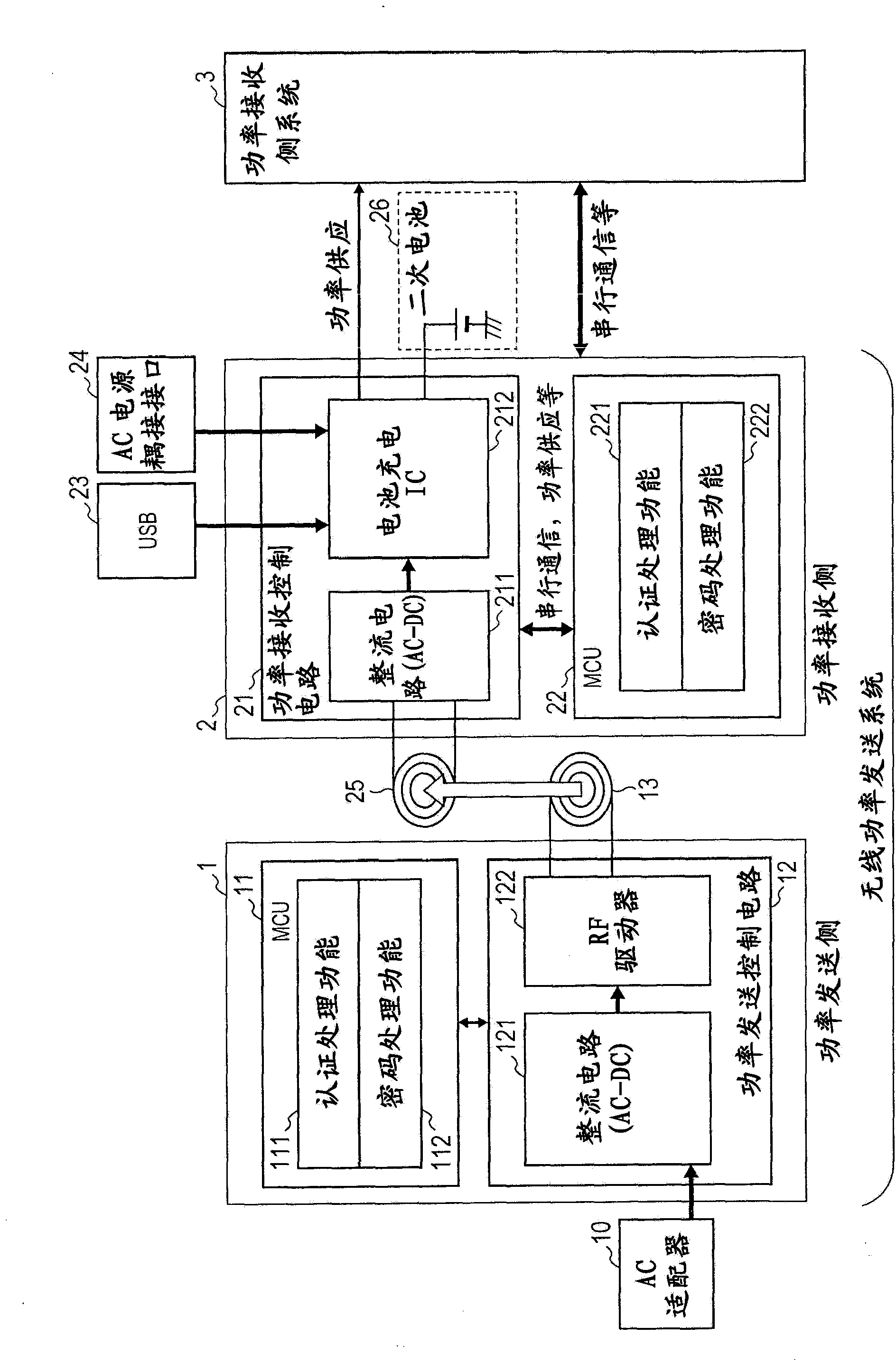
[0105] figure 1 is a diagram showing the configuration of a multifunctional cellular phone equipped with a semiconductor integrated circuit 212 for battery charge control according to the first embodiment.
[0106] figure 1 The shown multifunctional cellular phone includes a power transmitting circuit 1 , a power receiving circuit 2 and a power receiving side system 3 . Specifically, in figure 1 In the shown multifunctional cellular phone, an RF signal from the power transmitting side antenna coil 13 is received by the power receiving side antenna coil 25 , thereby performing charging of the secondary battery 26 and power supply to the power receiving side system 3 .
[0107] >
[0108] Such as figure 1 As shown, the power transmission circuit 1 on the transmission side of the wireless power transmission system is equipped with an AC power supply through an AC adapter 10 . The power transmission circuit 1 includes a microcontroller unit (MCU) 11 and a powe...
no. 2 example
[0182] >
[0183] Figure 6 is shown by figure 2 and 4 A diagram showing an operation in which the semiconductor integrated circuit 212 according to the second embodiment automatically selects a power source for use from among a plurality of power sources.
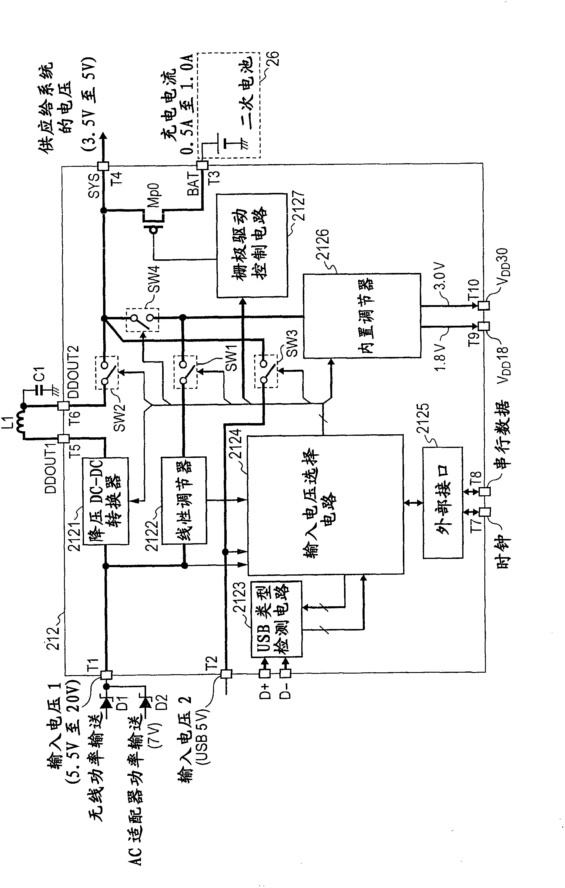
[0184] figure 2 and 4 The shown semiconductor integrated circuit 212 according to the first embodiment has implemented Figure 5 The initial operation of automatically selecting the power supply to be used for the first time from multiple power supplies is shown.
[0185] Such as Figure 6 shown, described below figure 2 and 4 The shown semiconductor integrated circuit 212 according to the second embodiment is capable of performing an initial operation of automatically selecting a power supply to be used from among a plurality of power supplies for the first time, and is capable of performing further automatic selection even in the case of additionally supplying subsequent power supply voltages. The voltage used f...
no. 3 example
[0201] >
[0202] Figure 8 is shown by figure 2 and 4 A diagram showing an operation in which the semiconductor integrated circuit 212 according to the third embodiment automatically selects a power supply to be used from among a plurality of power supplies.
[0203] Figure 6 An advantage of the illustrated operation of automatically selecting a power source to be used from a plurality of power sources according to the second embodiment is that the operation can be performed at figure 2 and 4 Nearly perfect execution is shown in the semiconductor integrated circuit 212 according to the second embodiment, but on the other hand, this operation has a problem in that the degree of freedom of automatic selection is low. That is, battery-operated electronic devices such as multifunctional cellular phones, tablet PCs, etc. need to increase the degree of freedom in the operation of automatically selecting a used power source from a plurality of power sources in order to cope wi...
PUM
 Abstract
Description
Claims
Application Information
 - Generate Ideas
- Intellectual Property
- Life Sciences
- Materials
- Tech Scout
- Unparalleled Data Quality
- Higher Quality Content
- 60% Fewer Hallucinations
Browse by: Latest US Patents, China's latest patents, Technical Efficacy Thesaurus, Application Domain, Technology Topic, Popular Technical Reports.
© 2025 PatSnap. All rights reserved.Legal|Privacy policy|Modern Slavery Act Transparency Statement|Sitemap|About US| Contact US: help@patsnap.com


