Liquid crystal display panel

A liquid crystal display panel and liquid crystal layer technology, applied in the direction of nonlinear optics, instruments, optics, etc., can solve the problems of not generally adopting vertical alignment, low pixel liquid crystal efficiency, etc., to improve liquid crystal efficiency, improve liquid crystal efficiency, and widen the use Effect

Active Publication Date: 2013-12-18
TCL CHINA STAR OPTOELECTRONICS TECH CO LTD
View PDF4 Cites 20 Cited by
  • Summary
  • Abstract
  • Description
  • Claims
  • Application Information

AI Technical Summary

Problems solved by technology

[0009] According to the introduction above, there are the following deficiencies in the existing technology: that is, in small-sized high-resolution panels, pixel liquid crystals designed using traditional methods have low efficiency, and the vertical alignment (VA) display mode is not commonly used.

Method used


Image

  • Liquid crystal display panel
  • Liquid crystal display panel
  • Liquid crystal display panel

Examples


Embodiment Construction

[0035] Hereinafter, the present invention will be described in detail with reference to the accompanying drawings.

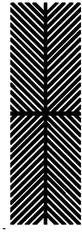
[0036] Figure 4 A schematic diagram showing a pixel electrode structure of a thin film transistor (TFT) array substrate of a liquid crystal display panel according to the present invention. The pixel electrode is arranged on the side of the liquid crystal layer where the thin film transistor is arranged, and is used for the array substrate. The pixel electrodes of the thin-film transistor (TFT) array substrate are designed in a "fishbone shape", that is, the entire electrode is divided into multiple display areas by vertically intersecting strip-shaped trunk electrode parts, and each display area is arranged with Strip-shaped branch electrodes.

[0037] Figure 5 A schematic structural view of the common electrode of the color filter substrate (CF) of the liquid crystal display panel according to the present invention is shown. The common electrode is arran...


PUM

PropertyMeasurementUnit
widthaaaaaaaaaa
widthaaaaaaaaaa
widthaaaaaaaaaa

Abstract

The invention relates to the technical field of liquid crystal display, in particular to a liquid crystal display panel. The efficiency of liquid crystals of the liquid crystal display panel can be improved. The liquid crystal display panel comprises an array substrate and a color film substrate. A liquid crystal layer is sandwiched between the array substrate and the color film substrate, a pixel electrode of the array substrate is of a multi-field structure, the multi-field structure comprises trunk portions and branch portions, and slits are formed in a common electrode of the color film substrate. Dark lines in the prior art can be narrowed by the slits. The liquid crystal display panel has the advantages that the common electrode for the color film substrate of the liquid crystal display panel is improved and is divided by gaps, so that the widths of the dark lines in the prior art can be greatly reduced, the efficiency of the liquid crystals of pixels in a vertical alignment mode is improved, and application of the vertical alignment mode to high-resolution liquid panels is broadened.

Description

technical field [0001] The invention relates to the technical field of liquid crystal display, in particular to a liquid crystal display panel for improving liquid crystal efficiency. Background technique [0002] Liquid crystal display has become the display terminal of mobile communication equipment, personal computer, television, etc. due to its advantages such as high display quality, low price, and portability. [0003] The currently widely used liquid crystal display is usually composed of upper and lower substrates and a middle liquid crystal layer, and the substrate is composed of glass and electrodes. [0004] If both the upper and lower substrates have electrodes, a display with a vertical electric field mode can be formed, such as a twisted nematic (Twist Nematic, TN) mode, a vertical alignment (Vertical Alignment, VA) mode, and a multi-domain vertical display developed to solve a narrow viewing angle. Alignment (Multidomain Vertical Alignment, MVA) mode. [000...

Claims


Application Information

Patent Timeline
Patent Type & Authority Applications(China)
IPC IPC(8): G02F1/1343
CPCG02F1/133707G02F1/134309G02F1/134318G02F1/133514
Inventor 郝思坤
Owner TCL CHINA STAR OPTOELECTRONICS TECH CO LTD
Why Eureka
Try Eureka