Reflection type liquid crystal display device with controlled directors

a liquid crystal display and control device technology, applied in the field of reflection-type liquid crystal display devices, can solve the problems of reducing light utilization efficiency, disadvantageously having a lower display contrast than display devices, etc., and achieves the effects of improving the contrast ratio of display, increasing the azimuth dependence of viewing angle characteristics, and improving brightness of a white display sta

Active Publication Date: 2013-07-09
SHARP KK
View PDF22 Cites 5 Cited by
  • Summary
  • Abstract
  • Description
  • Claims
  • Application Information

AI Technical Summary

Benefits of technology

[0038]According to the present invention, in a reflection-type liquid crystal display device which includes a liquid crystal layer whose state is switchable between a light-scattering state and a light-transmitting state, the scattering efficiency of the liquid crystal layer in the light-scattering state can be improved without increasing the azimuth dependence of the viewing angle characteristics. Therefore, the brightness of a white display state can be improved, and thus, the contrast ratio of display can be improved. Alternatively, by decreasing the thickness of the liquid crystal layer, the driving voltage can be decreased to a low level while maintaining the brightness of the white display state.
[0039]In the present invention, the directors of the liquid crystal regions are controlled by the alignment films. Therefore, the liquid crystal regions can be arranged in the liquid crystal layer at a higher density than in a conventional technique in which the directors are controlled according to the shape of the liquid crystal regions (the shape of the small sections). As a result, the scattering characteristic of the liquid crystal layer can be improved more effectively.
[0040]According to the present invention, a reflection-type liquid crystal display device such as described above can be manufactured using a simple method without increasing the complexity of the manufacturing process.

Problems solved by technology

However, when such a display mode is used, it is necessary to provide polarizers over the surfaces of the liquid crystal panel, and absorption of light by the polarizers disadvantageously decreases the light utilization efficiency.
A reflection-type liquid crystal display device which uses a scattering-transmitting mode, such as the display device 300, disadvantageously has a lower display contrast than display devices which use other display modes.

Method used


Image

  • Reflection type liquid crystal display device with controlled directors
  • Reflection type liquid crystal display device with controlled directors
  • Reflection type liquid crystal display device with controlled directors

Examples


Embodiment Construction

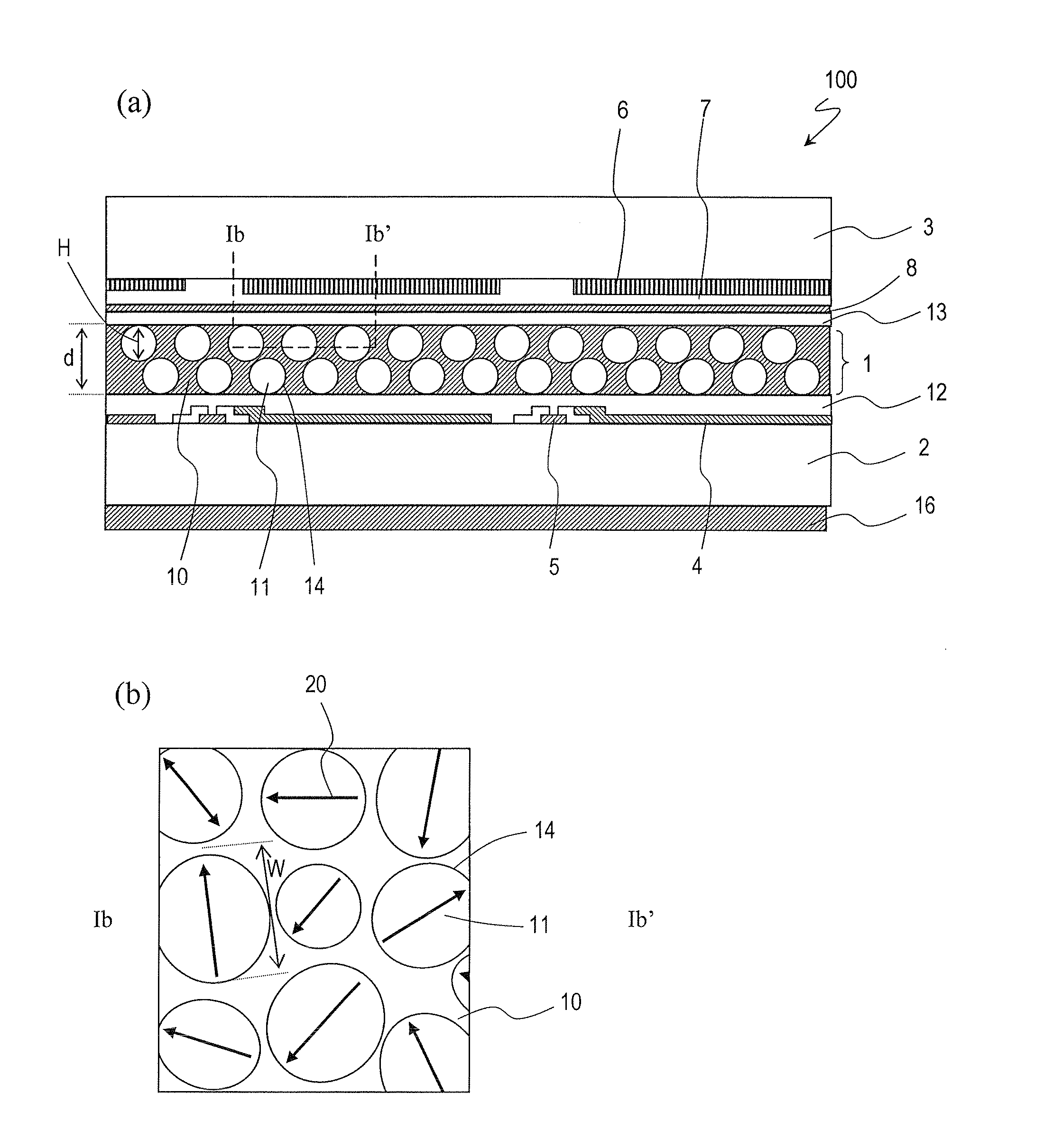
[0052]In a reflection-type liquid crystal display device of the present invention, at least two liquid crystal regions which have directors in a plane parallel to the liquid crystal layer are included in one pixel. The directors of these liquid crystal regions are oriented in different directions from one another.

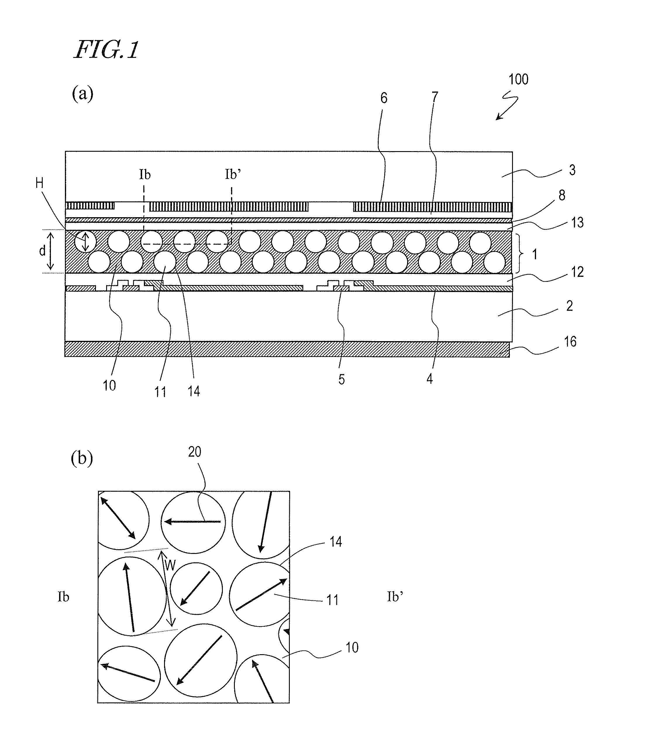
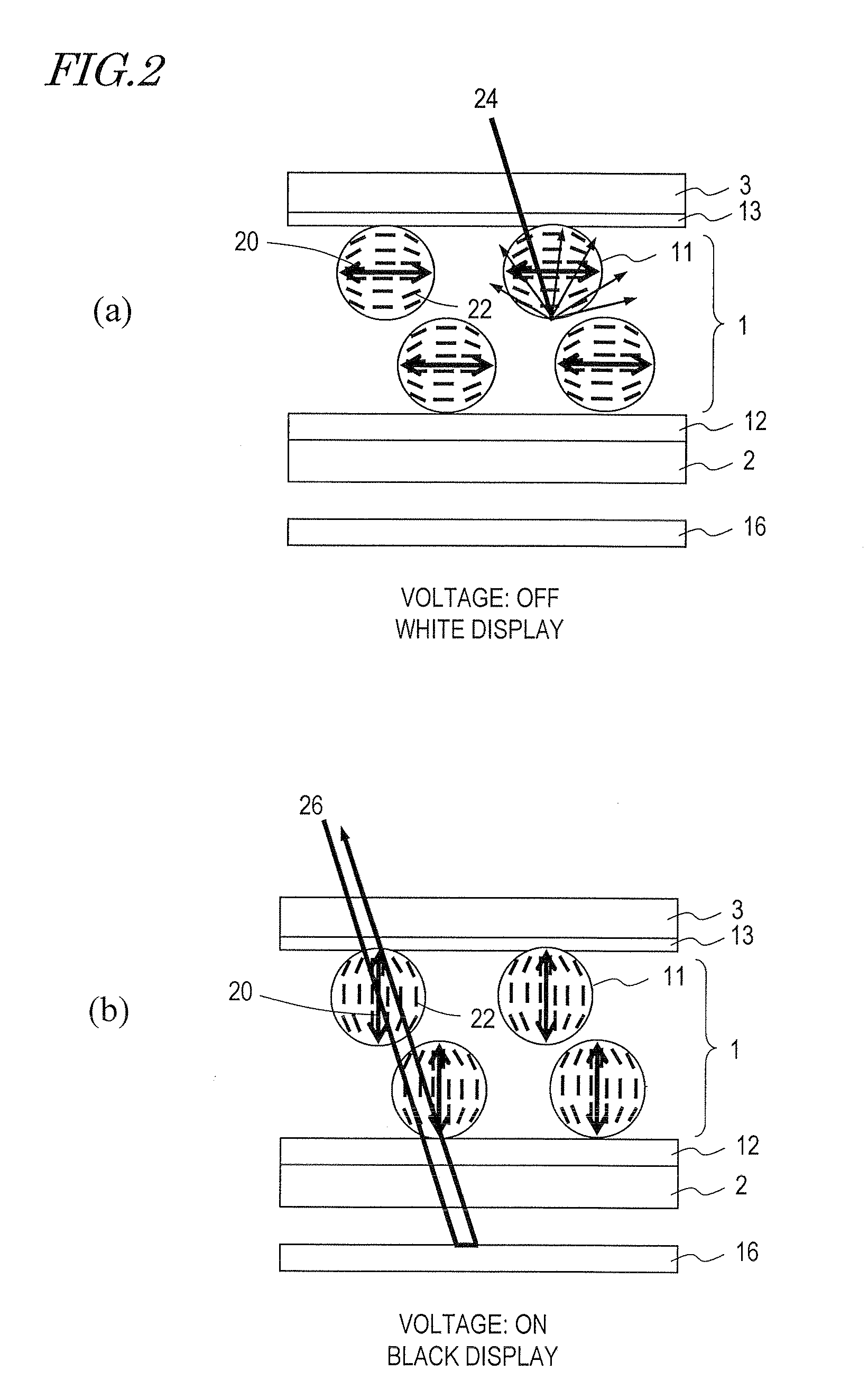
[0053]According to the present invention, the directors of the liquid crystal regions are in a plane parallel to the liquid crystal layer. Therefore, in a light-scattering state (white display state), the difference in refractive index between the liquid crystal regions and the walls that separate the liquid crystal regions is the maximum, so that brighter display can be realized. Alternatively, the thickness of the liquid crystal layer can be decreased while the display brightness is maintained. As a result, the driving voltage can be decreased to a low level.

[0054]Since the directors of the plurality of liquid crystal regions are oriented in different directions, the azim...


PUM

PropertyMeasurementUnit
surface free energyaaaaaaaaaa
diameteraaaaaaaaaa

Abstract

A liquid crystal display device includes a liquid crystal layer 1 whose state is switchable between a light-transmitting state and a light-scattering state, a front substrate 3 and a rear substrate 2 between which the liquid crystal layer 1 is held, a pair of electrodes 4, 8 between which the liquid crystal layer 1 is interposed and which are configured to apply a voltage across the liquid crystal layer 1, and first and second alignment films 13, 12 respectively provided between the liquid crystal layer 1 and the front substrate 3 and between the liquid crystal layer 1 and the rear substrate 2. The liquid crystal layer 1 includes, in each of the pixels, a continuous wall 10, a plurality of small sections 14 separated by the wall 10, and a plurality of liquid crystal regions 11, each of which is formed in any one of the plurality of small sections 14. The plurality of liquid crystal regions 11 include first and second liquid crystal regions 11 which have directors 20 in a plane parallel to the liquid crystal layer 1. The directors 20 of the first and second liquid crystal regions 11 are oriented in different directions.

Description

[0001]This application is the U.S. national phase of International Application No. PCT / 22009 / 004008, filed 21 Aug. 2009, which designated the U.S. and claims priority to Japanese Application No. 2008-215682, filed 25 Aug. 2008, the entire contents of each of which are hereby incorporated by reference.TECHNICAL FIELD[0002]The present invention relates to a reflection-type liquid crystal display device.BACKGROUND ART[0003]In conventional reflection-type liquid crystal display devices, display modes such as TN (Twisted Nematic) mode and STN (Super Twisted Nematic) mode are used. However, when such a display mode is used, it is necessary to provide polarizers over the surfaces of the liquid crystal panel, and absorption of light by the polarizers disadvantageously decreases the light utilization efficiency.[0004]A newly-proposed display mode which does not require the use of polarizers is a mode in which display is performed by switching the liquid crystal layer by application of a volt...

Claims


Application Information

Patent Timeline
Patent Type & Authority Patents(United States)
IPC IPC(8): G02F1/1335G02F1/1337
CPCG02F1/1334G02F1/133553G02F1/1337G02F1/133305G02F2001/133765G02F1/133765G02F1/1335
Inventor ASAOKA, YASUSHISATOH, EIJIMINOURA, KIYOSHIFUJIWARA, SAYURI
Owner SHARP KK
Why Eureka
Try Eureka