Color filter substrate, LCD (liquid crystal display) panel and manufacturing methods thereof
A color filter and liquid crystal panel technology, applied in optics, nonlinear optics, instruments, etc., can solve the problem of increasing the time and work flow of production line changeover, which is not conducive to rapid production line changeover and lean production, and waste of production materials and other problems, to achieve the effect of reducing glue mixing time, saving steps and required time, and reducing production costs
- Summary
- Abstract
- Description
- Claims
- Application Information
AI Technical Summary
Problems solved by technology
Method used
Image
Examples
Embodiment 1
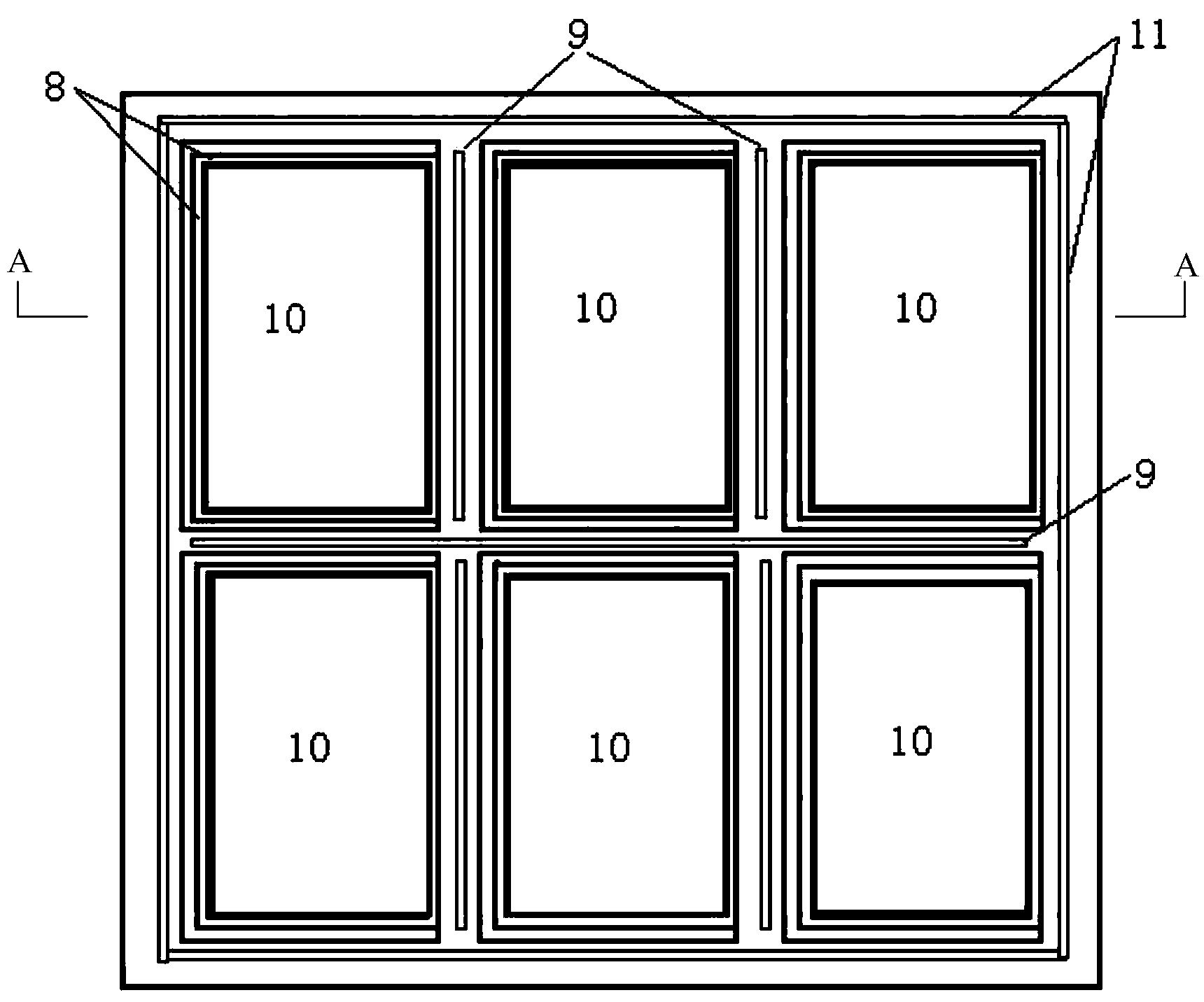
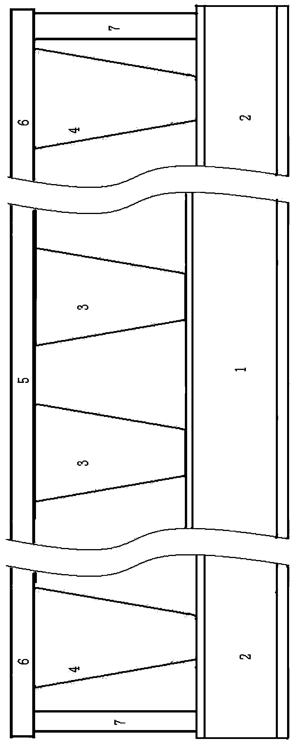
[0041] like figure 1 and 2 As shown, taking the above-mentioned first liquid crystal panel design method as an example, in the cell process (Cell), when the spacer (PS) is installed in the last process on the color filter substrate side, the color filter substrate The first spacer 3 is set in the display area 5 of the color filter substrate while the frame glue coating area 6 (including the main frame glue coating area 8, the auxiliary frame glue coating area 9 and the ring frame glue coating area 11 ) is also provided with a second spacer 4, wherein the height of the second spacer 4 is 0.3 μm higher than that of the first spacer 3, and the shapes of the first spacer 3 and the second spacer 4 are truncated cones, Wherein the material of the first spacer 3 and the second spacer 4 is polyimide. Then, the frame glue coating area 6 of the color filter substrate is coated with an adhesive 7 that does not contain a support, and then the liquid crystal material is dripped on the co...
Embodiment 2
[0044] like figure 1 and 2 As shown, taking the above-mentioned first liquid crystal panel design method as an example, in the cell process (Cell), when the spacer (PS) is installed in the last process on the color filter substrate side, the color filter substrate The first spacer 3 is set in the display area 5 of the color filter substrate while the frame glue coating area 6 (including the main frame glue coating area 8, the auxiliary frame glue coating area 9 and the ring frame glue coating area 11 ) is also provided with a second spacer 4, wherein the height of the second spacer 4 is 0.8 μm higher than that of the first spacer 3, and the shapes of the first spacer 3 and the second spacer 4 are cylindrical, Wherein the material of the first spacer 3 and the second spacer 4 is polyimide. Then, the frame glue coating area 6 of the color filter substrate is coated with an adhesive 7 that does not contain a support, and then the liquid crystal material is dripped on the color ...
Embodiment 3
[0047] like figure 1 and 2 As shown, taking the above-mentioned first liquid crystal panel design method as an example, in the cell process (Cell), when the spacer (PS) is installed in the last process on the color filter substrate side, the color filter substrate The first spacer 3 is set in the display area 5 of the color filter substrate while the frame glue coating area 6 (including the main frame glue coating area 8, the auxiliary frame glue coating area 9 and the ring frame glue coating area 11 ) also set the second spacer 4, wherein the height of the second spacer 4 is 0.4 μm higher than that of the first spacer 3, and the shape of the first spacer 3 and the second spacer 4 is a continuous strip shape, wherein the material of the first spacer 3 and the second spacer 4 is polyimide. Then, the frame glue coating area 6 of the color filter substrate is coated with an adhesive 7 that does not contain a support, and then the liquid crystal material is dripped on the color ...
PUM
| Property | Measurement | Unit |
|---|---|---|
| Height | aaaaa | aaaaa |
Abstract
Description
Claims
Application Information
 - R&D
- Intellectual Property
- Life Sciences
- Materials
- Tech Scout
- Unparalleled Data Quality
- Higher Quality Content
- 60% Fewer Hallucinations
Browse by: Latest US Patents, China's latest patents, Technical Efficacy Thesaurus, Application Domain, Technology Topic, Popular Technical Reports.
© 2025 PatSnap. All rights reserved.Legal|Privacy policy|Modern Slavery Act Transparency Statement|Sitemap|About US| Contact US: help@patsnap.com


