
Air conditioning system based on energy efficiency assessment and optimized control and method thereof

An air-conditioning system and energy efficiency evaluation technology, applied in heating and ventilation control systems, heating and ventilation safety systems, heating methods, etc., can solve the problem of large horse-drawn carts, the difficulty in realizing real-time matching of water flow and cooling capacity, and the reduction of COP of refrigeration units And other issues

Active Publication Date: 2013-12-18
HANGZHOU ZHANDE SOFTWARE TECH
View PDF3 Cites 24 Cited by
  • Summary
  • Abstract
  • Description
  • Claims
  • Application Information

AI Technical Summary

Problems solved by technology

According to statistics, the electricity consumption of central air-conditioning accounts for more than 70% of the total electricity consumption of various buildings, and the central air-conditioning equipment fluctuates under 70% load 97% of the time, and the actual air-conditioning load is only about 50% of the equipment capacity on average. As a result, the phenomenon of "big horses and small carts" appeared, causing huge waste
Moreover, during the operation of the air conditioner, each motor is fixed at full speed at power frequency for a long time, and the flow of circulating water is adjusted through the throttle valve and bypass valve. It is difficult to achieve real-time matching of water flow and cooling capacity, resulting in water system In the long-term high energy consumption operation state of "large flow, small temperature difference", and reduce the COP of the refrigeration unit

Method used


Image

  • Air conditioning system based on energy efficiency assessment and optimized control and method thereof
  • Air conditioning system based on energy efficiency assessment and optimized control and method thereof
  • Air conditioning system based on energy efficiency assessment and optimized control and method thereof

Examples


Embodiment Construction

[0046] The present invention will be described in detail with reference to the accompanying drawings.

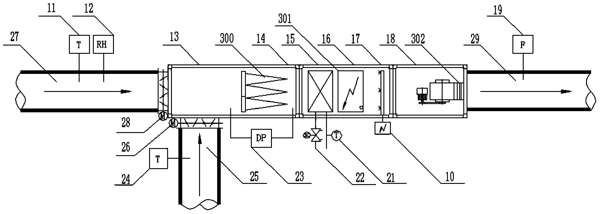
[0047] Such as figure 2 , 3 As shown, the air-conditioning system based on energy efficiency evaluation and optimal control includes a cabinet in which PLC1 (programmable logic controller), display screen 2, relay 3, power supply 4, power socket 5, transformer 6, and air circuit breaker 7 are installed. , communication interface 8, output terminal 9 and input terminal 10; among them, power supply 4, power socket 5, air circuit breaker switch 7, transformer 6 are connected sequentially, and transformer 6 is connected to each device inside the cabinet to realize power supply; PLC1 is respectively connected to the communication interface 8 is connected with display screen 2.

[0048] The device also includes the implementation control structure of the air conditioning unit and the chilled water supply and return pipes:

[0049] A fresh air temperature sensor 24 and a fresh ...


PUM


Abstract

The invention relates to the field of the assessment and control on the energy efficiency of air conditioning systems and aims at providing an air conditioning system based on energy efficiency assessment and optimized control and a method thereof. A fresh air temperature sensor, a return air temperature sensor, a return air humidity sensor, a supply air flow sensor and a supply water temperature sensor of the system are connected to a PLC (Programmable Logic Controller) through an input end of a cabinet, and the PLC is connected to a motor, an electronic dynamic flow balance valve, a fresh air valve and a return air valve of an air blower of an air conditioning unit through an output end. According to the system and the method, intelligent valves are mounted at a chilled water system and an air conditioning terminal, chilled water supply temperature, chilled water supply pressure, outdoor temperature and terminal switching signals serve as input and output points; all signals and flows serve as communication points of the intelligent valves MODBUS, energy efficiency coefficients of all systems are calculated according to an assessment method and then are subjected to optimization analysis in a control device, intelligent control data are changed, the energy efficiency of the system is increased greatly, and then, the effects of saving energy and lowering consumption are reached.

Description

technical field [0001] The invention relates to the field of energy efficiency evaluation and control of an air conditioning system. More specifically, the present invention relates to an air conditioning system based on energy efficiency evaluation and optimal control and its method. Background technique [0002] Central air conditioning is the main energy consumption part of modern buildings. According to statistics, the electricity consumption of central air-conditioning accounts for more than 70% of the total electricity consumption of various buildings, and the central air-conditioning equipment fluctuates under 70% load 97% of the time, and the actual air-conditioning load is only about 50% of the equipment capacity on average. As a result, the phenomenon of "big horses and small carts" appeared, resulting in huge waste. Moreover, during the operation of the air conditioner, each motor is fixed at full speed at power frequency for a long time, and the flow of circula...

Claims


Application Information

Patent Timeline
IPC IPC(8): F24F11/00
Inventor 任世琛王小华许丹丹方飞龙麻剑锋
Owner HANGZHOU ZHANDE SOFTWARE TECH
Learn More