
Anti-blocking and anti-gas drainage pump for coal-bed gas mechanical valve

A technology of mechanical valves and drainage pumps, which is applied in the direction of mechanical equipment, liquid variable capacity machinery, pumps, etc., can solve the problems of drainage pump failure, high maintenance costs, coal powder blockage, etc., to avoid rigid wear and improve wear resistance , the effect of reducing leakage

Inactive Publication Date: 2013-12-18
XI'AN PETROLEUM UNIVERSITY
View PDF6 Cites 9 Cited by
  • Summary
  • Abstract
  • Description
  • Claims
  • Application Information

AI Technical Summary

Problems solved by technology

At present, the drainage function mainly adopts the rod well pump used in conventional oil and gas fields. This structure is greatly affected by the coal powder carried out in the well water, and the phenomenon of pump jamming and blockage often occurs. The main manifestations are: 1) The coal powder particles entering the oil pipe settle Finally, it is easy to accumulate in the gap between the plunger and the pump barrel, which accelerates the wear of the pump barrel and the probability of pump jamming; 2) The floating valve and the fixed valve are easy to block the pulverized coal, causing the drainage pump to fail, shortening the pump inspection cycle, and the maintenance cost is high

Method used


Image

  • Anti-blocking and anti-gas drainage pump for coal-bed gas mechanical valve
  • Anti-blocking and anti-gas drainage pump for coal-bed gas mechanical valve
  • Anti-blocking and anti-gas drainage pump for coal-bed gas mechanical valve

Examples


Embodiment Construction

[0029] The following combined with the attachment, the structural principles and working principles of the present invention are further described in detail.

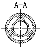
[0030] like figure 1 It shows that the present invention provides a coalbed methane mechanical valve to prevent blocking the gas drainage pump., Compose 23 of the fixed valve hood and 26 tail pipe joints, the lower end of the pump pump 2 is connected to the pump 5, the lower end of the pump tube 5 is connected to the pump pump 19, and the pump pump is connected to the pump.The fixed valve joint 21 is connected, and the fixed valve joint 21 is connected to the tail pipe 26 through the fixed valve hood 23; the inner pump lever assembly is composed of tie rods 4, valve stem guide connector 7, mechanical valve lever 8, guide cone valve 18 connector, can be ableWith the on -bottom of the oil pumping rod, it provides a source of power for the drainage pump; the soft secret sealing colonum assembly is connected by the plunger 9, t...


PUM


Abstract

The invention discloses an anti-blocking anti-gas drainage pump for a coal-bed gas mechanical valve. An upper coupling of a pump barrel is connected with the pump barrel; the pump barrel is connected with a lower coupling of the pump barrel; the lower coupling of the pump barrel is connected with a fixed valve joint through a lengthened short joint; the fixed valve joint is connected with a tail tube joint through a fixed valve cover; pull rods are arranged in the inner cavities of the upper coupling of the pump barrel and the pump barrel; the pull rods are connected with a valve rod reducing joint; the pull rods are connected with a valve rod guide joint; the valve rod guide joint is connected with a mechanical valve pull rod; the mechanical valve pull rod is connected with a guide conical valve; the guide conical valve is matched with a mechanical valve base; the mechanical valve base is connected with a lower abrasion ring through a valve base joint; a plunger mandrel is connected with a plunger upper joint; the pull rods are used for driving the mechanical valve pull rod to move upwards, the guide conical valve moves upwards and is meshed with the mechanical valve base, a plunger assembly moves upwards, a fixed valve ball is opened, and well water enters the pump through a helical outlet, so that coal powder is prevented from being accumulated; the guide conical valve is separated from the mechanical valve base forcibly, and liquid in the pump barrel enters an oil tube through an overflow groove, so that pump clamping and blocking are avoided, and the pump detection period is prolonged.

Description

Technical field [0001] The present invention belongs to the field of coalbed methane mining, and specially involves a coalbed methane mechanical valve anti -air drainage pump. Background technique [0002] The coal seam gas, also known as the coal seam gas, is a methane -based natural gas generated by the coal seam during the long coalization of geological history.my country's coalbed methane resources are abundant, and coalbed methane as a new type of clean energy and high -quality chemical raw materials can not only alleviate my country's tension energy demand, reduce the occurrence of coal mine accidents, but also reduce the emissions of greenhouse gas, realize green mining of green mining, Essence [0003] The coal sedental gas drainage requires a continuous pressure reduction process. A large range of coal seams as much as possible can reduce the pressure through drainage, so that a large amount of adsorption gas in the coal seams leaves from the restraint of the coal seam s...

Claims


Application Information

Patent Timeline
Patent Type & Authority Applications(China)
IPC IPC(8): F04B53/14F04B53/10F04B47/12
Inventor 屈文涛郭怡潇袁比飞孙艳萍孙旭光
Owner XI'AN PETROLEUM UNIVERSITY
Learn More