
Power generation device of turbine expander

A technology of turbo expander and power generation device, which is applied in the directions of machines/engines, mechanical equipment, engine components, etc., to achieve broad market prospects, development space, and simple methods.

Inactive Publication Date: 2013-12-18
HARBIN DONGAN ENGINE GRP
View PDF6 Cites 1 Cited by
  • Summary
  • Abstract
  • Description
  • Claims
  • Application Information

AI Technical Summary

Problems solved by technology

However, at present, the technology of using compressed air to generate electricity is still blank.

Method used


Image

  • Power generation device of turbine expander

Examples


Embodiment Construction

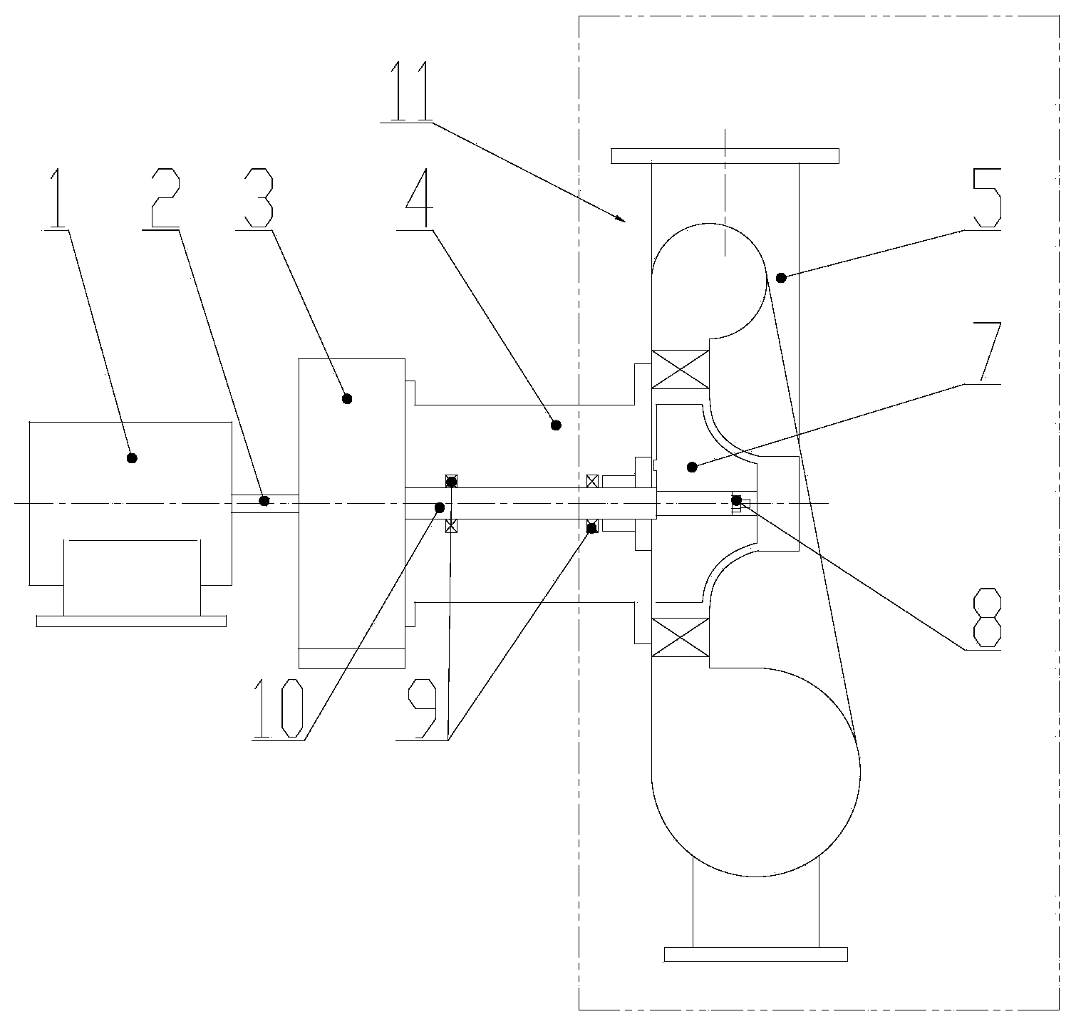
[0008] As shown in the figure, the turbo expander power generation device includes a generator 1, a speed reducer 3, and a turbo expander 11. The rotor of the generator 1 is directly connected to the output end of the speed reducer 3 through a coupling 2; the turbo expander One end of the turbine shaft 10 in 11 is fixed to the turbine impeller, and the other end is connected to the input end of the reducer 3. The turbine shaft 10 is installed on the bearing casing 4 through the bearing 9, and the two ends of the bearing casing 4 are installed on the reducer respectively. 3 and the turbo expander 11, the volute 5 of the turbo expander 11 is connected to the gas supply system. The generator 1 is a three-phase AC synchronous generator, and the turbine impeller 7 can be connected to the turbine shaft 10 by welding or bolts 8 . Described bearing 9 is two.

[0009] When the present invention is working, the compressed air enters the turbo expander 11 through the volute 5 of the tur...


PUM


Abstract

The invention relates to a power generation device of a turbine expander. The power generation device of the turbine expander comprises a power generator 1, a reducer 3 and the turbine expander 11, wherein a rotor of the three-phase alternating-current synchronous power generator 1 is directly connected with an output end of the reducer 3 through a coupler 2, one end of a turbine shaft 10 of the turbine expander 11 is fixedly connected with a turbine impeller, the other end of the turbine shaft 10 is connected with an input end of the reducer 3, and the turbine shaft 10 is arranged on a bearing casing 4 through a bearing 9. According to the power generation device of the turbine expander, disclosed by the invention, the turbine expander is connected with the power generator, compressed air does work, the work can be converted into high-quality electric energy, the purpose of converting low-quality electric energy into the high-quality electric energy can be realized, the method is simple, convenient and pollution-free, and the power generation device has a wide market prospect and a wide development space.

Description

technical field [0001] The invention relates to a power generation device, in particular to a turbo expander power generation device. Background technique [0002] The turbo expander converts energy by using the change of the working fluid velocity when it flows. The working fluid expands in the circulation part of the turbo expander to obtain kinetic energy, and the external work is output by the working wheel shaft, thus reducing the internal energy of the working fluid at the outlet of the expander. and temperature. So at present, the main application of turbo expander is in the field of refrigeration, and it is rarely used in the field of power generation. [0003] In recent years, with the development of the wind power industry, many wind power stations have been established in China and the world in a short period of time. However, due to insufficient technical capabilities and poor quality of wind power generation, nearly 2 / 3 of the electric energy cannot be combined...

Claims


Application Information

Patent Timeline
Patent Type & Authority Applications(China)
IPC IPC(8): F01D15/10F01D5/02
Inventor 何民冯占祥钟明磊刘莉娜脱烨刘丛红时晓军孙海龙张永川程治刚邢家伟
Owner HARBIN DONGAN ENGINE GRP
Learn More